-
- Project Summary:The Dao Clock
- 1.Initial idea of the project:“Lazy clock” is not lazy; it is technology connecting people with nature
- 2.Further considerations and final naming:Dao Clock
- 3.From Idea to Sketch:Project Description
- 3D design of the Dao Clock
- Overview of the 3D design
- 1.The ID&MD of Dao Clock
- 2.The ID of Dao Clock
- ********Final adjust Update*********
- The PCB design of the Dao Clock
- Overview of the PCB design
- 1.Design and Manufacturing of PCB_Part1
- 2.Design and Manufacturing of PCB_Part2_Main Control Circuit Board
- ********Final adjust Update*********
- The PCB Manufacturing
- From Gerber to G-Code
- Machining the PCB and checking the Circuit
- Make the BOM for Dao Clock PCB
- Solder components onto the PCB
- Embedding program and Testing
- Original design files of my final project
- Final project presentation
- Epilogue
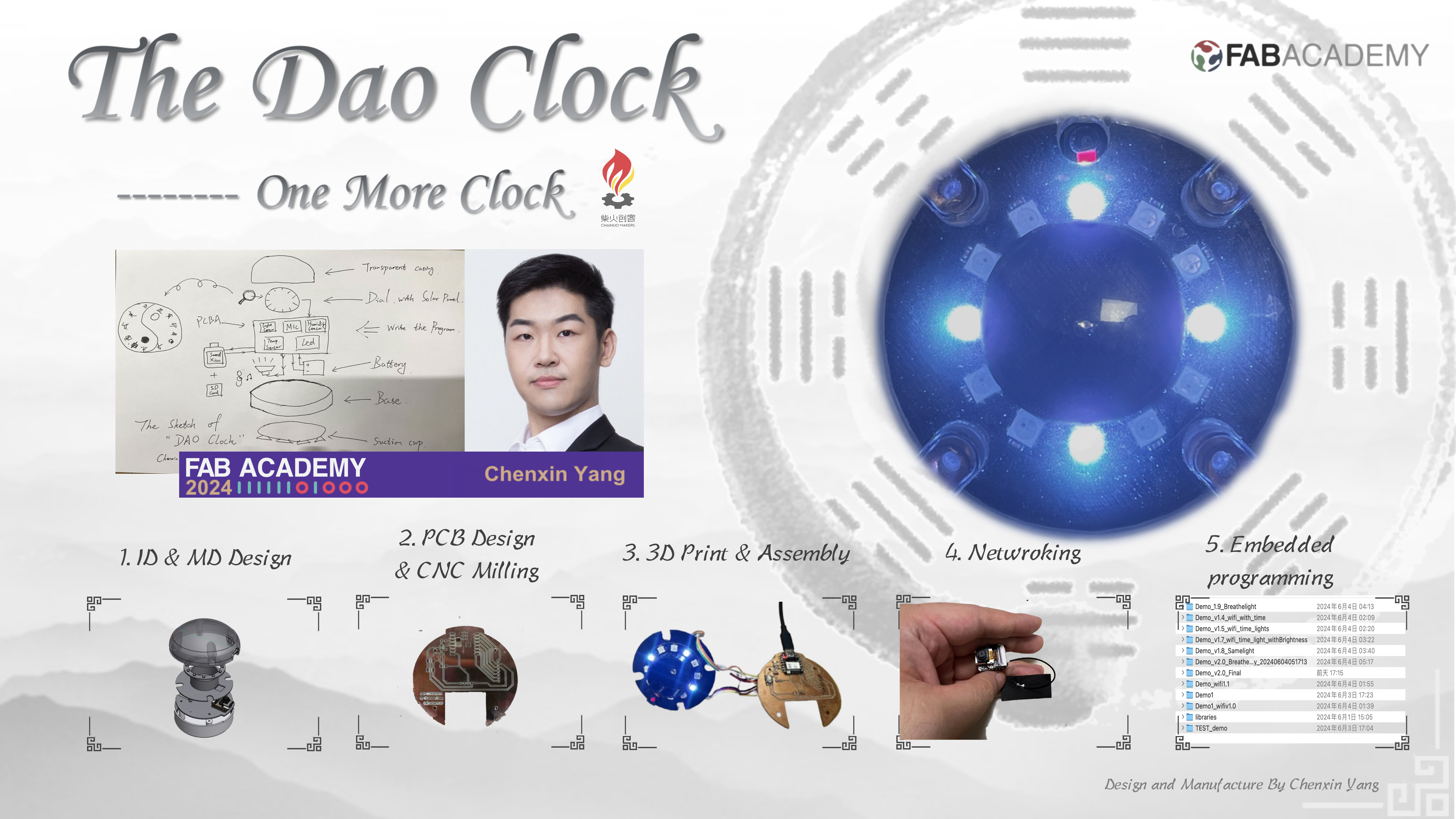
My Final Project: Dao Clock
Project Summary:The Dao Clock
1.Initial idea of the project:“Lazy clock” is not lazy; it is technology connecting people with nature
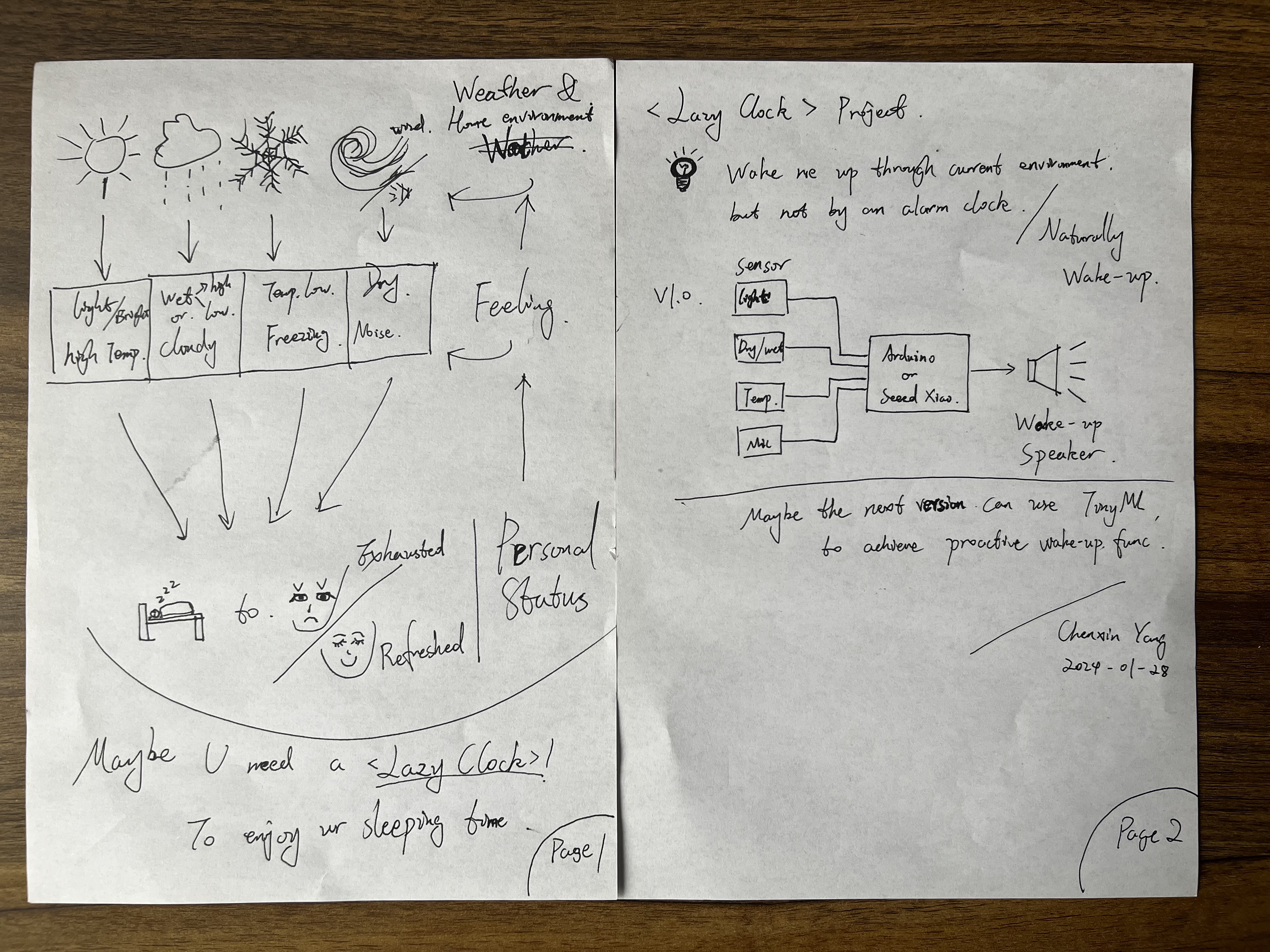
I recently came up with an innovative project idea, inspired by my daily experiences.
I noticed that when my alarm clock rings, I don't really want to get out of bed.
Instead, I often decide when to actually leave bed based on the environmental conditions.
This led me to conceive a device called the "Lazy Clock," designed to wake me up naturally from my surroundings, a concept I refer to as "Naturally Wake-Up."
In the initial phase of this project, I plan to create a simple demo to validate the feasibility of my idea.
I realized that to make the "Lazy Clock" truly effective, it needs to be able to understand and respond to subtle changes in the environment.
Building on this, I intend to apply my knowledge of TinyML (Tiny Machine Learning) to this project.
My goal is to use TinyML algorithms for training, creating a personalized feature that wakes up users based on environmental changes.
To achieve this, my first focus will be on data collection and processing.
I plan to use various sensors to capture natural changes in the environment, such as sound, light, and temperature, and convert these data into a format suitable for machine learning models. Next, I will design and train a lightweight machine learning model capable of recognizing specific environmental changes as signals to wake up the user.
Regarding hardware, I will carefully select appropriate devices to deploy my model. Considering the power consumption and computational limits of TinyML, this might be challenging. I plan to use a small microcontroller, equipped with necessary environmental sensors.
Once my model is successfully deployed, I will ensure the system can monitor environmental changes in real time and trigger an alarm or other wake-up mechanisms when it detects the predetermined wake-up signal. I will also thoroughly test and optimize the entire system to ensure it can accurately and reliably wake up the user at the right moment.
I am extremely excited about this project. It's not only challenging but also has the potential to provide a more natural and personalized wake-up experience for people. I am looking forward to seeing my "Lazy Clock" idea become a reality and make a practical impact.
2.Further considerations and final naming:Dao Clock
After further reflection, I learned to respect nature from traditional Chinese culture.
In ancient China, people recorded time using sundials, which displayed time through the changes in natural light.
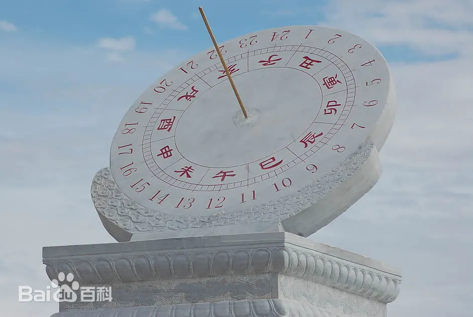
Definition of Sundial
TEN HEAVENLY STEMS AND TWELVE EARTHLY BRANCHES
The Twelve Chinese Zodiac Hours:Zi, Chou, Yin, Mao, Chen, Si, Wu, Wei, Shen, You, Xu, Hai
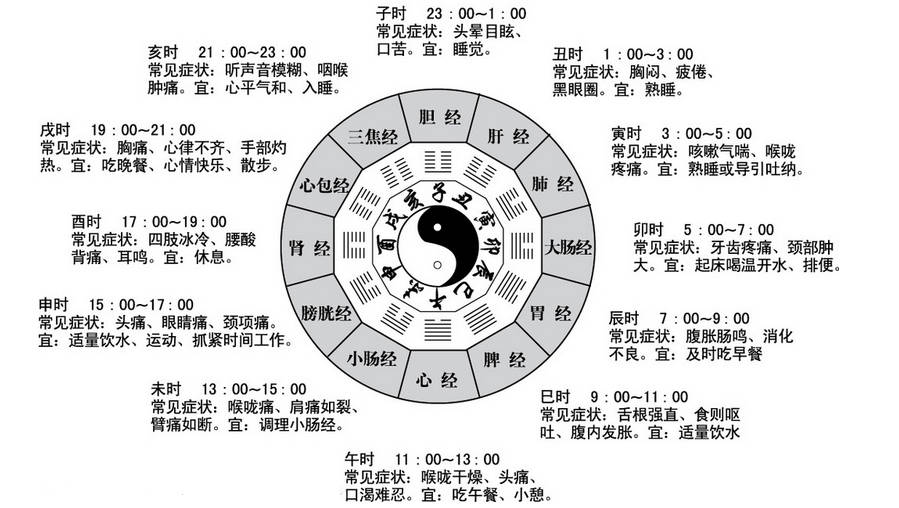
This provided inspiration for my dial design. I chose the Dao as the symbol of the Dao Clock, which is a symbol of time and nature.
From Idea to Sketch:Project Description
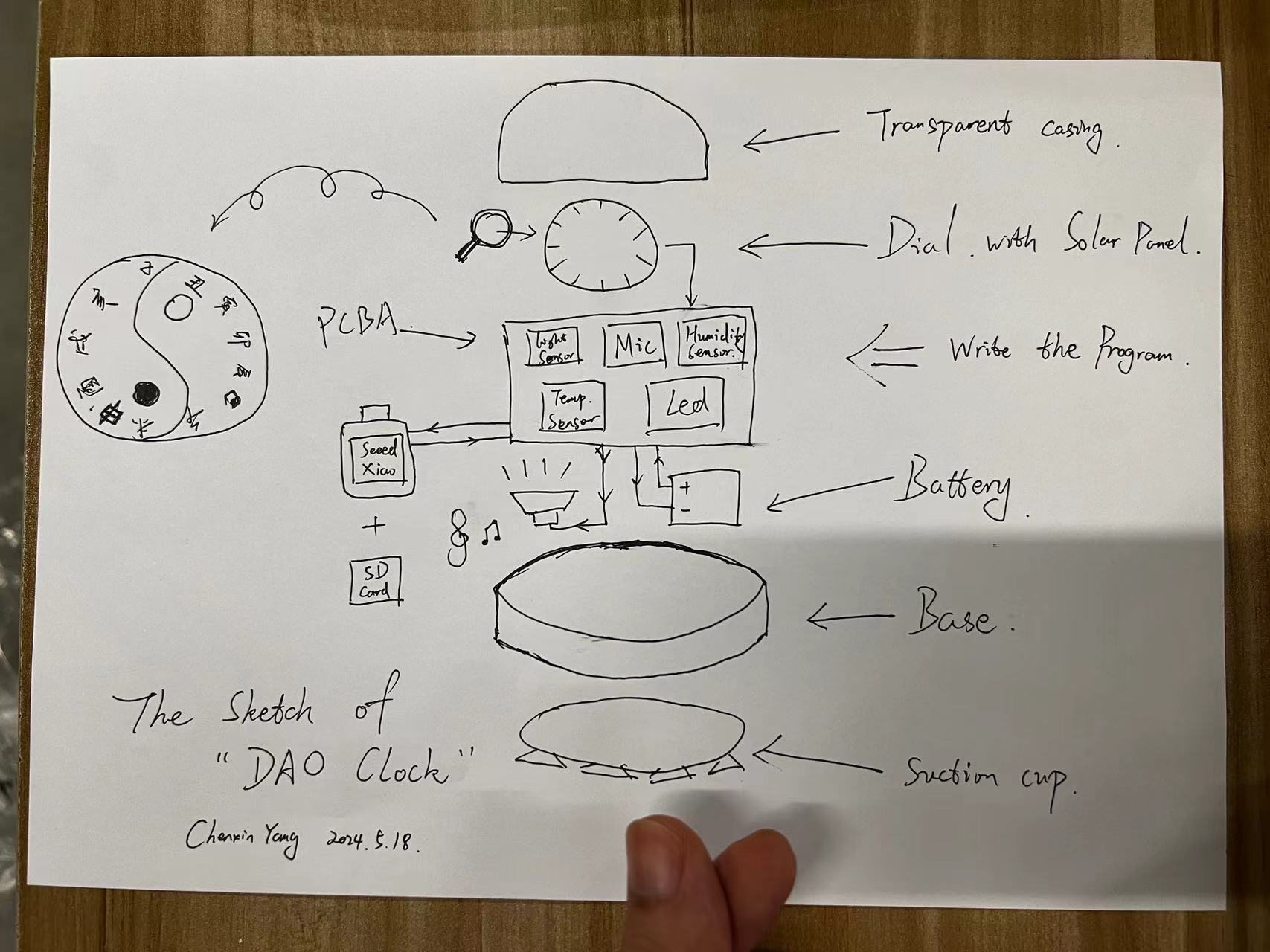
In the design of Dao Clock, I will use a light sensor, microphone, humidity sensor, and temperature sensor as output devices.
Using the Seeed Xiao as the processor, I will load the desired program.
When the suitable environment is achieved, it will read from the SD card to play my favorite music and wake me up through the speaker as the output device.
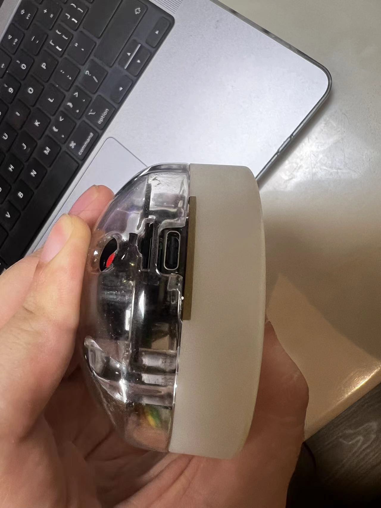
For the casing, I will use transparent plastic material to ensure that these sensors are not affected during operation.
Additionally, its suction cup will be used to attach Dao Clock to my window.
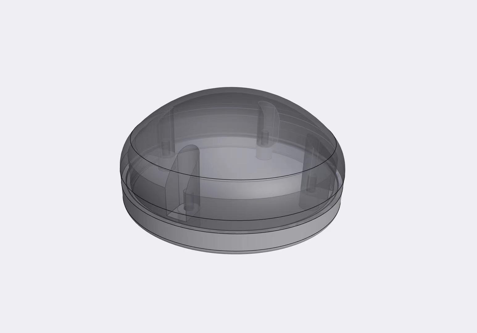
3D design of the Dao Clock
Overview of the 3D design
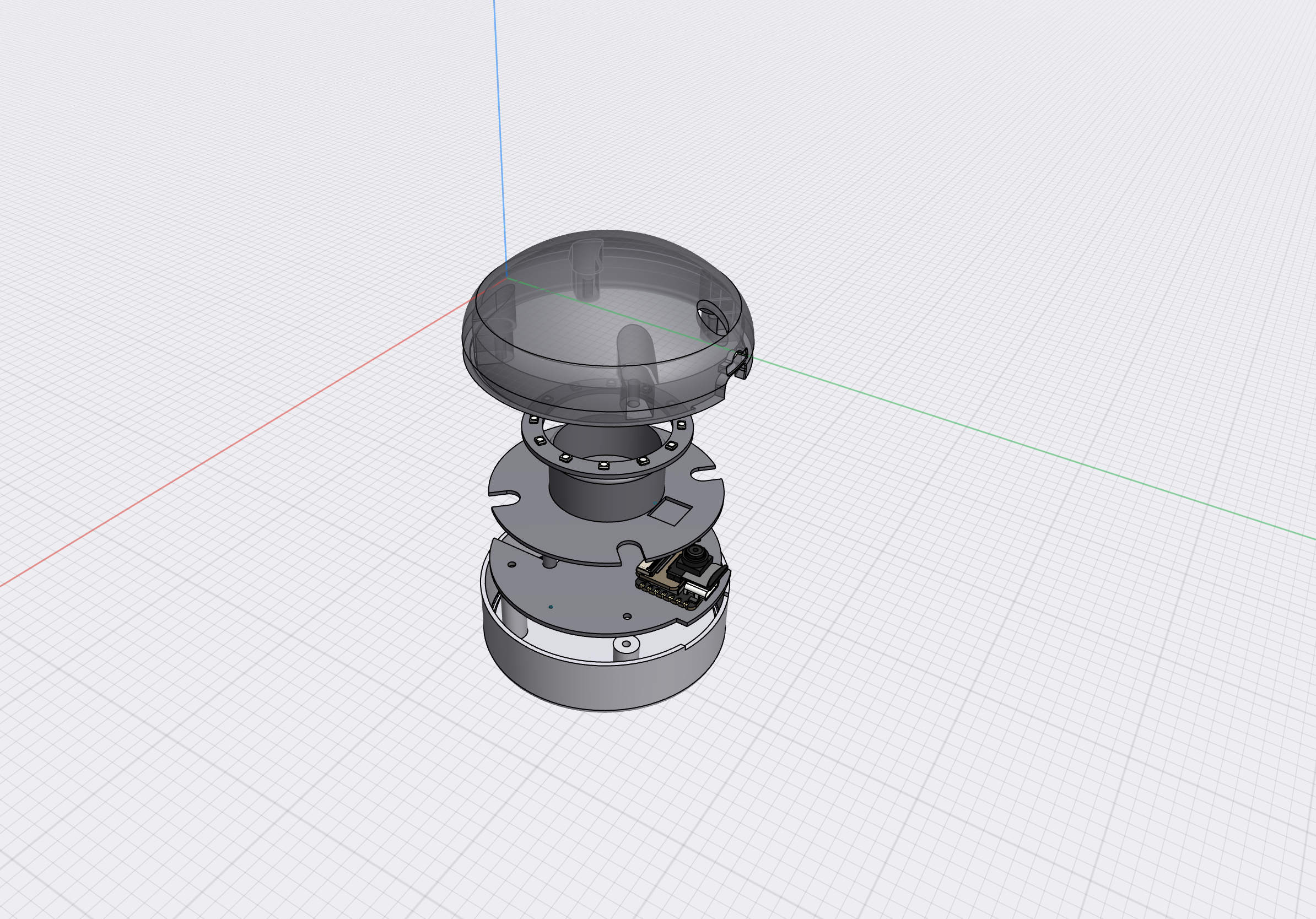
Combining the internal structural design of the circuit board, I finally completed the adjustments for each structural section.
5.27 Update:
Due to miscalculations of the various component sizes on the circuit board, which led to design defects, I had to readjust the design.
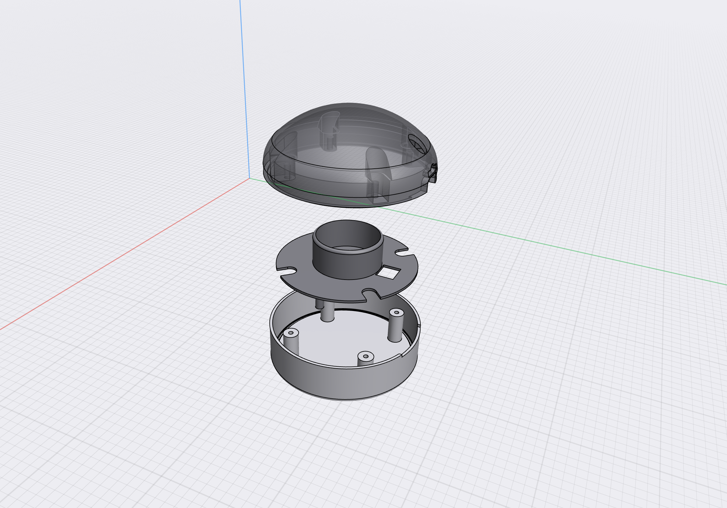
It includes three parts:
| **Name** | **Qty** | **Description or SPEC** | **Price** | **Link** |
|---|---|---|---|---|
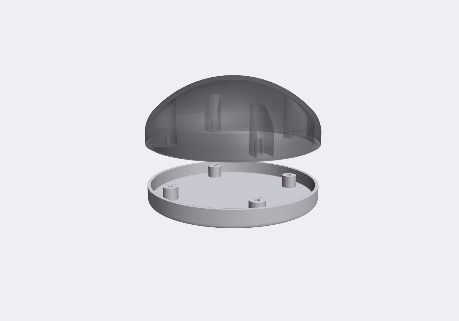
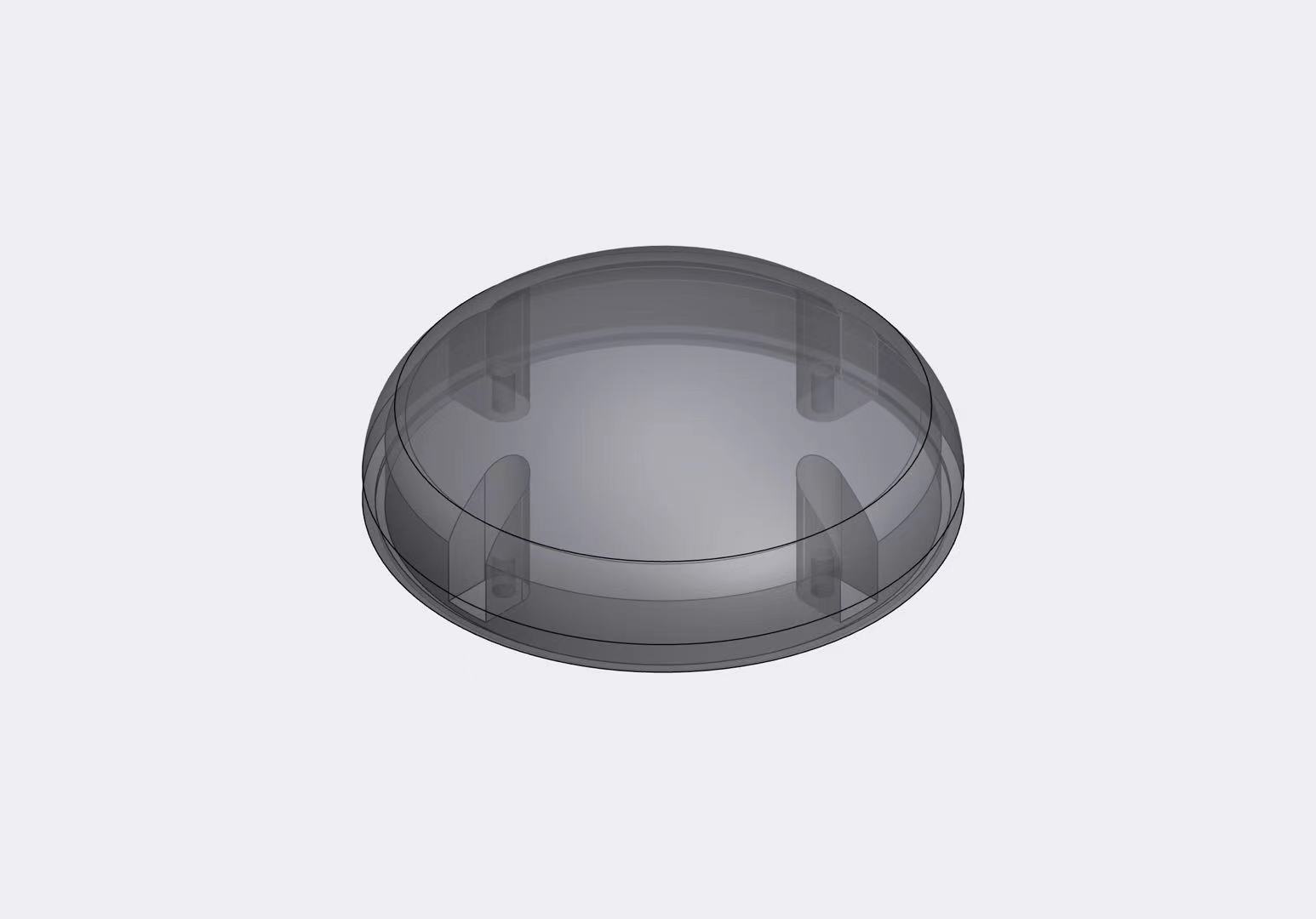
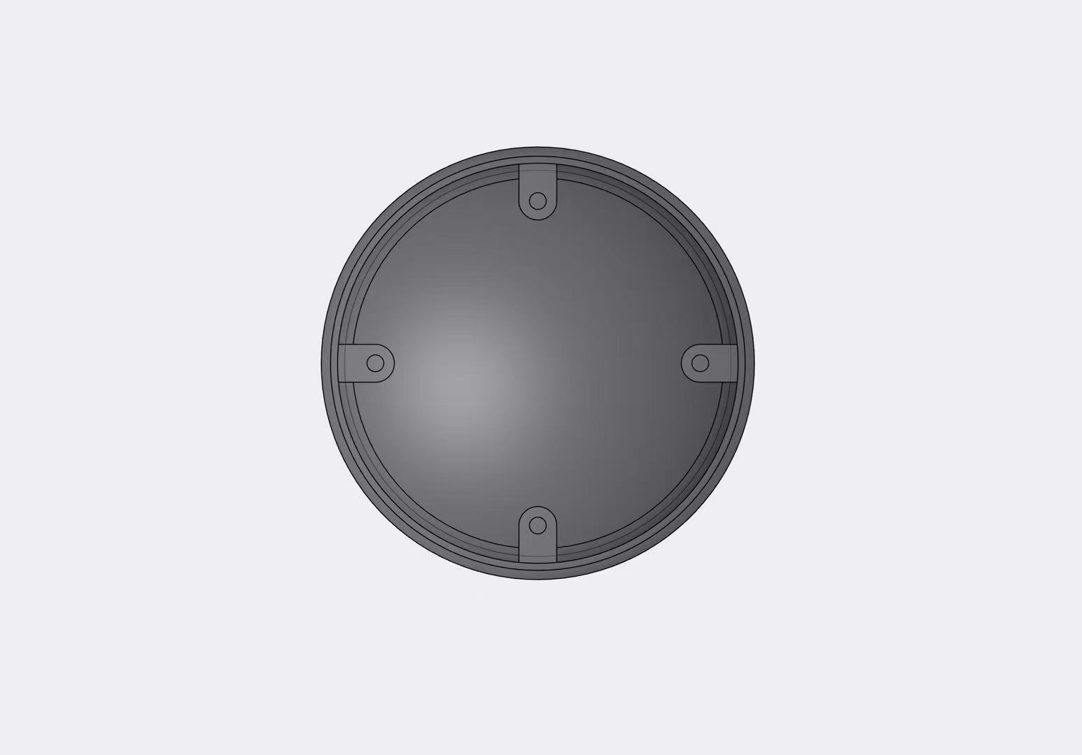
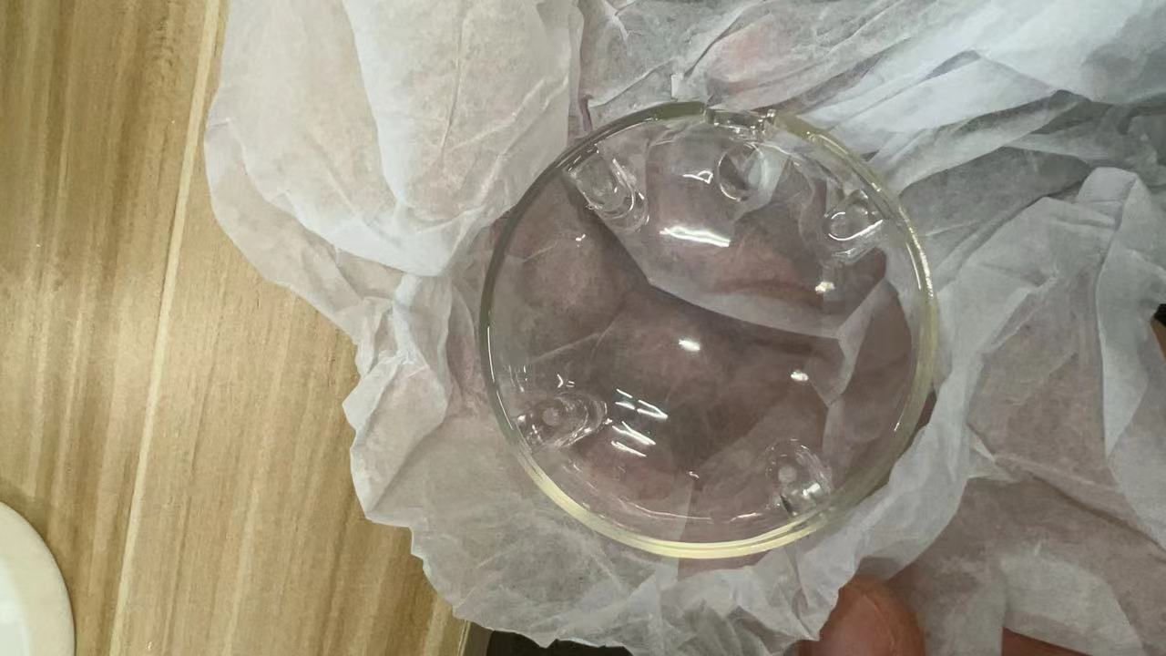
| Transparent top cover | 1 | The transparent material is used to protect the device and prevent the components from being exposed. This material is chosen to showcase the Neopixel lighting effects while allowing the light sensor to function effectively. |
$11.50 | Click to buy |
| Middle support structure | 1 | The cylindrical protective layer is specially designed to support the components of PCB_Part1 and prevent the Neopixels from interfering with the light sensor during operation. |
0.10 $ | Printed by myself |
| Base structure | 1 | The base is used to protect the components and provides space for placing the battery. |
3.00 $ | Click to buy |
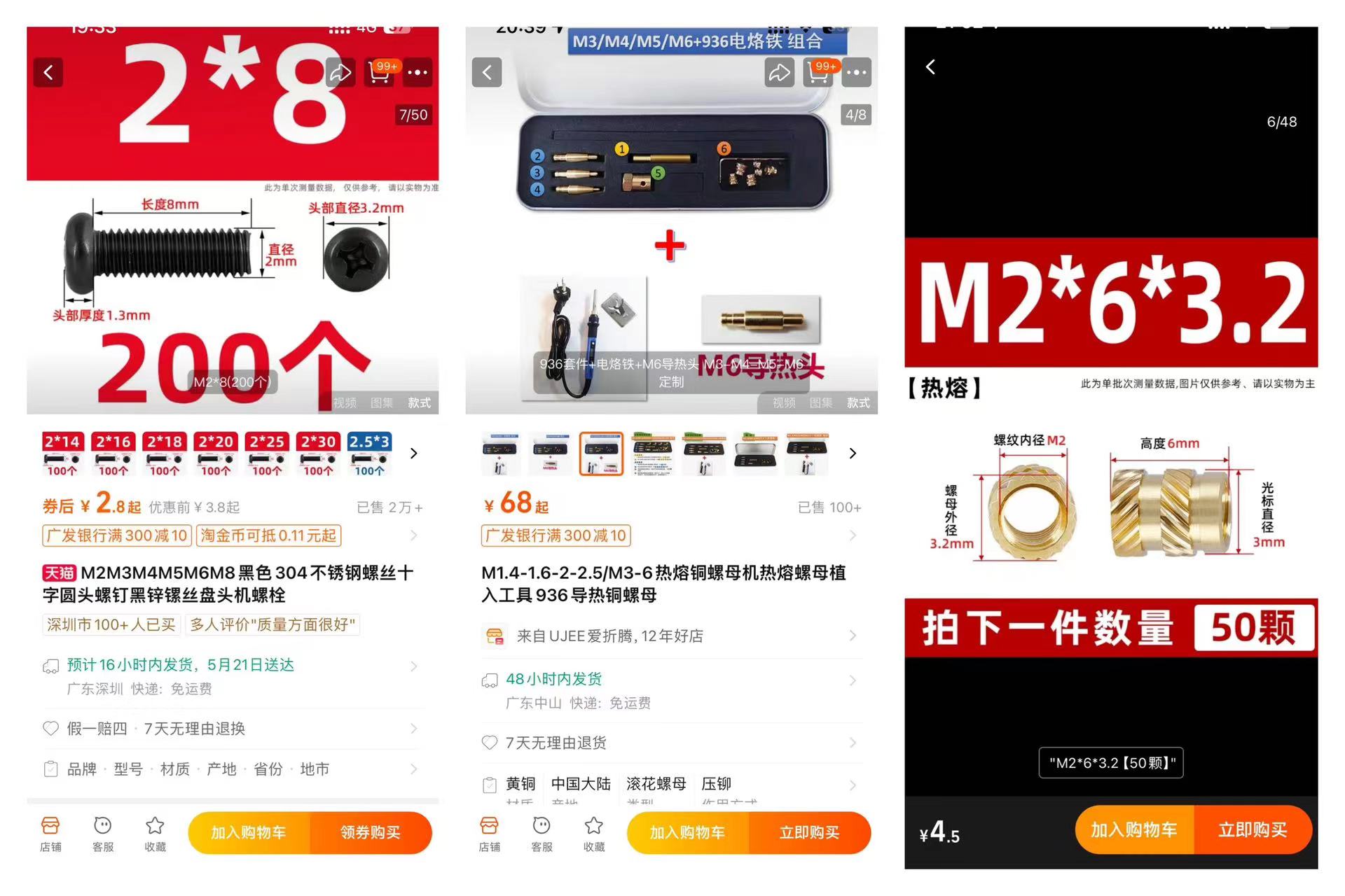
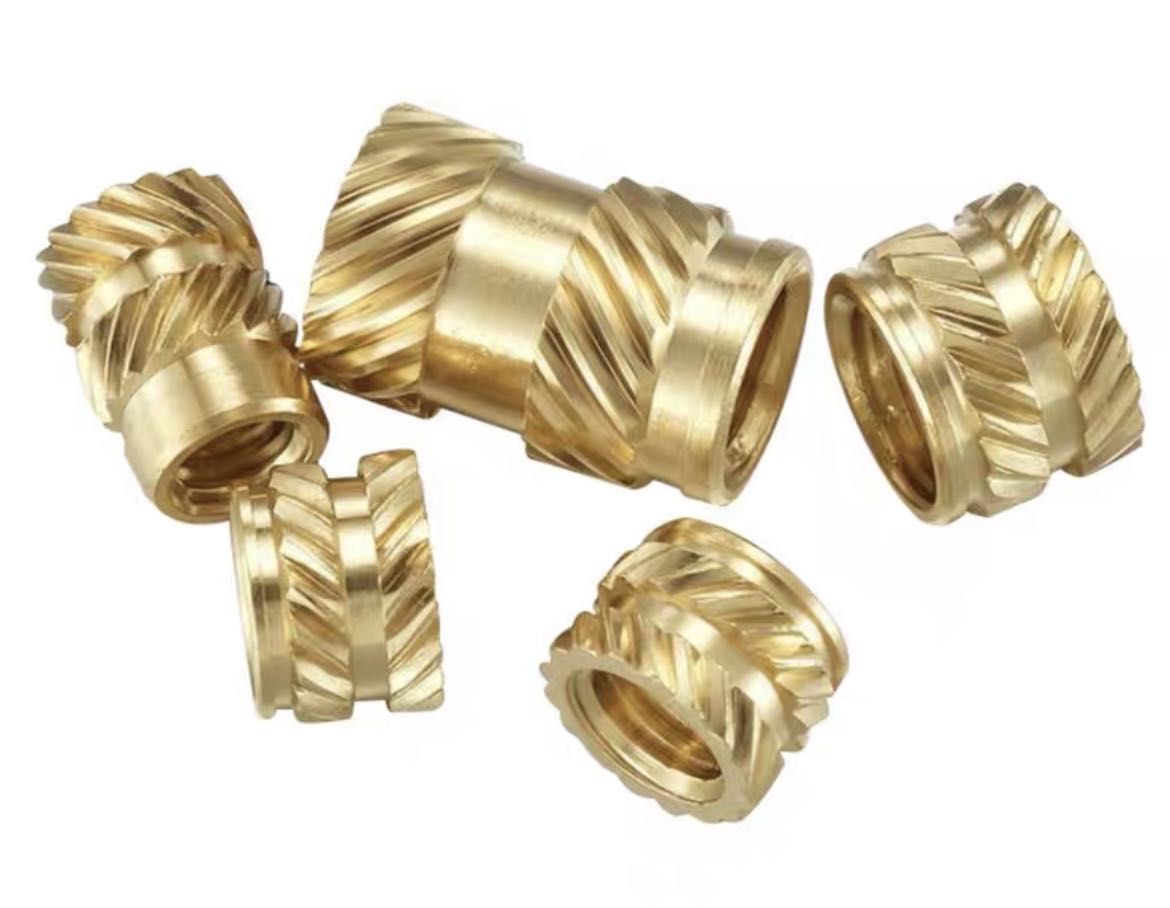
| Hot melt copper nut | 4 |
a metal insert embedded into plastic to provide a durable, reusable threaded hole |
2.28 $ | Click to buy |
1.The ID&MD of Dao Clock
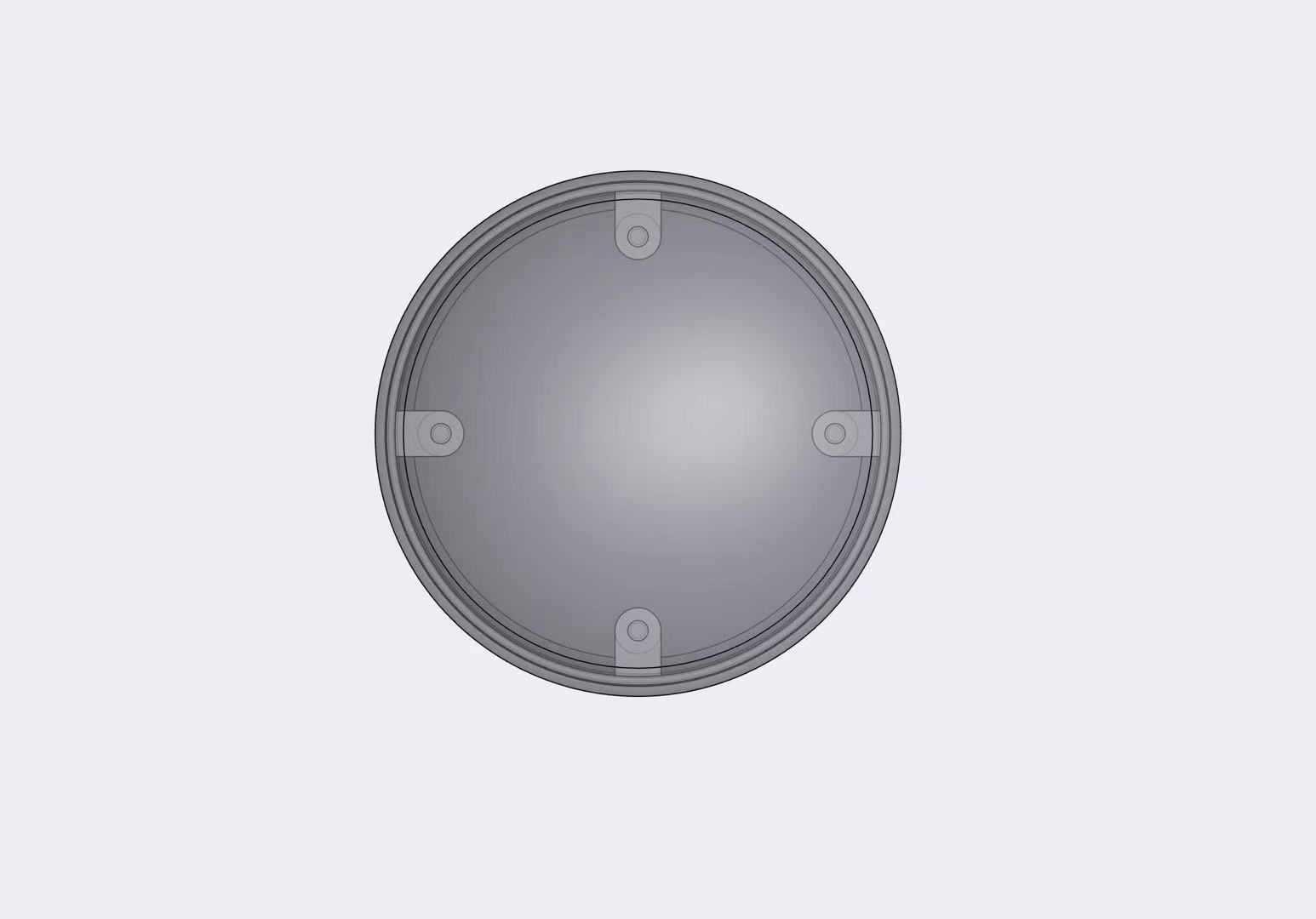
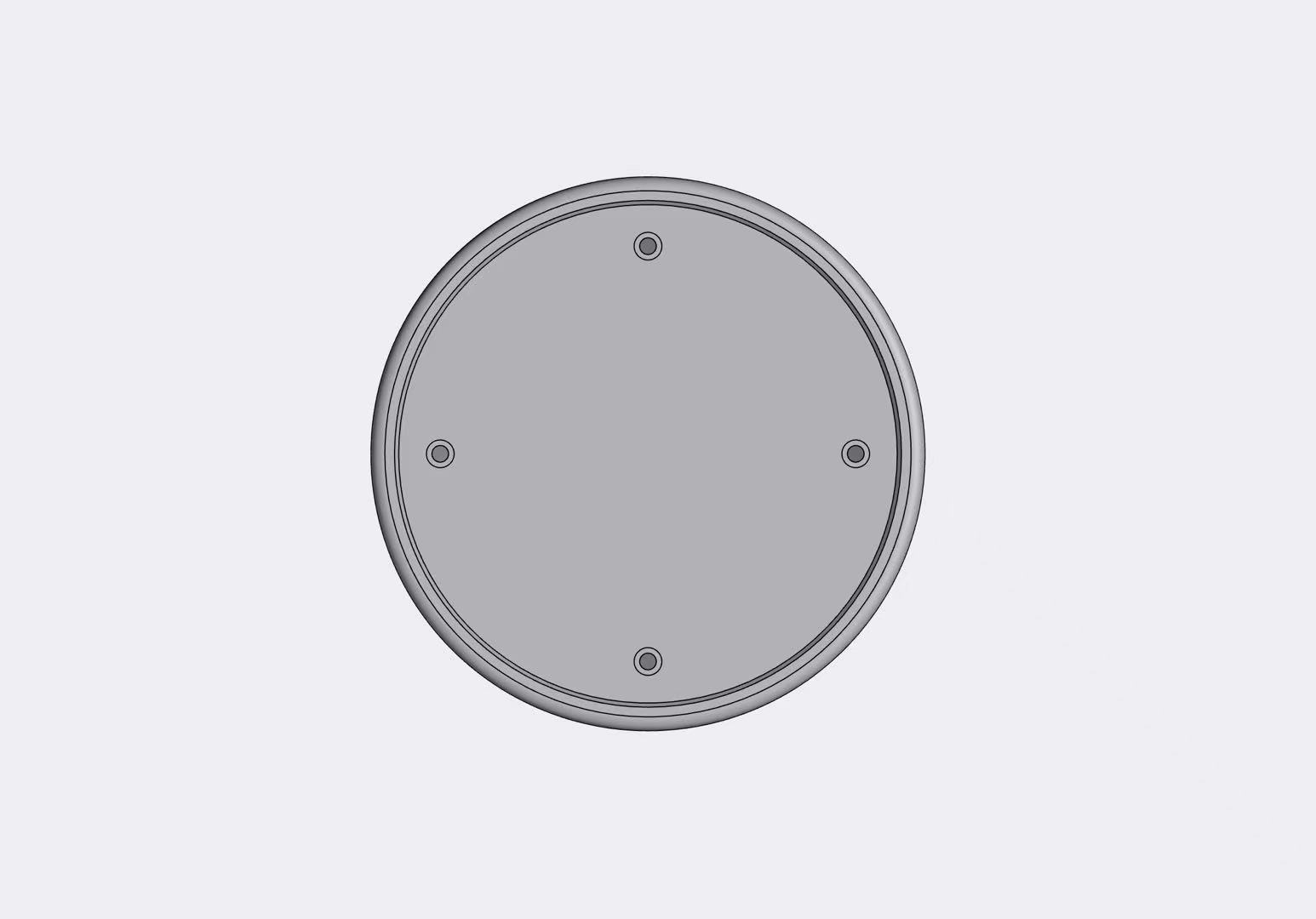
1. Base Design
Based on the dimensions provided by this suction cup, I designed the base and made it fit into my base.
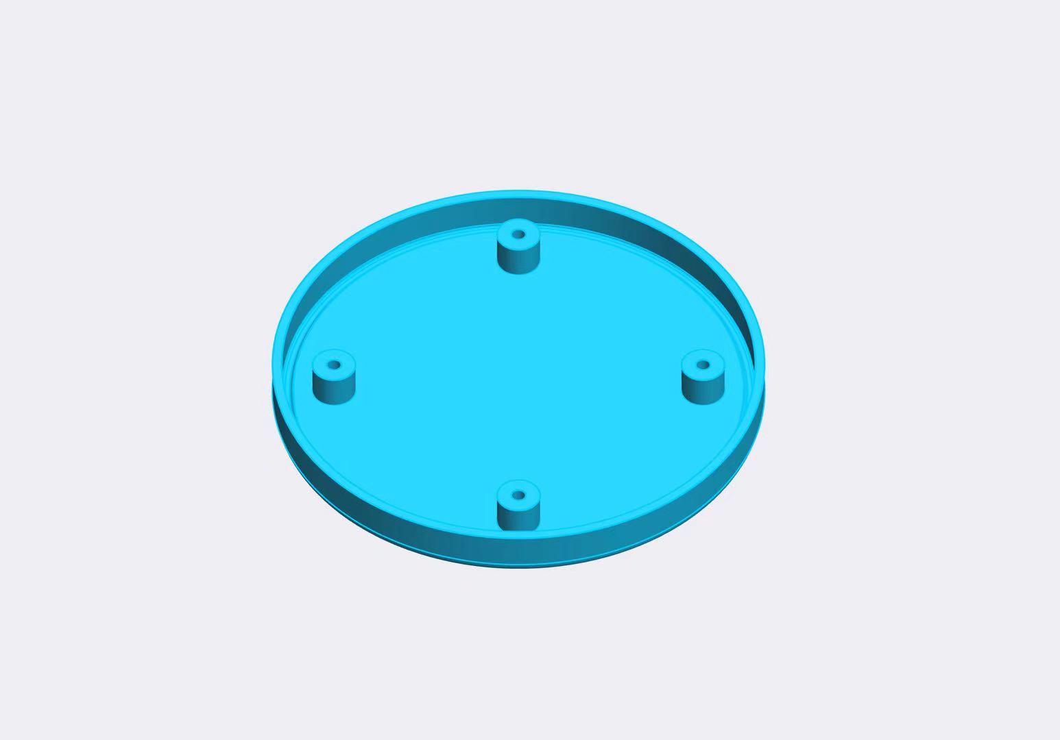
At the same time, I considered making holes in certain positions to ensure that the microphone and speaker work without interference.
I designed embedded grooves to make the installation of the casing and base more precise.
I chose to use screws and nuts for the connection, so I designed screw holes.
It is necessary to explain that since the casing may need to be disassembled for debugging and testing, I designed a hot melt nut process on the casing.
This makes it easy to connect the casing and the base, and it is more solid.
2.Manufacture & Assemble the parts
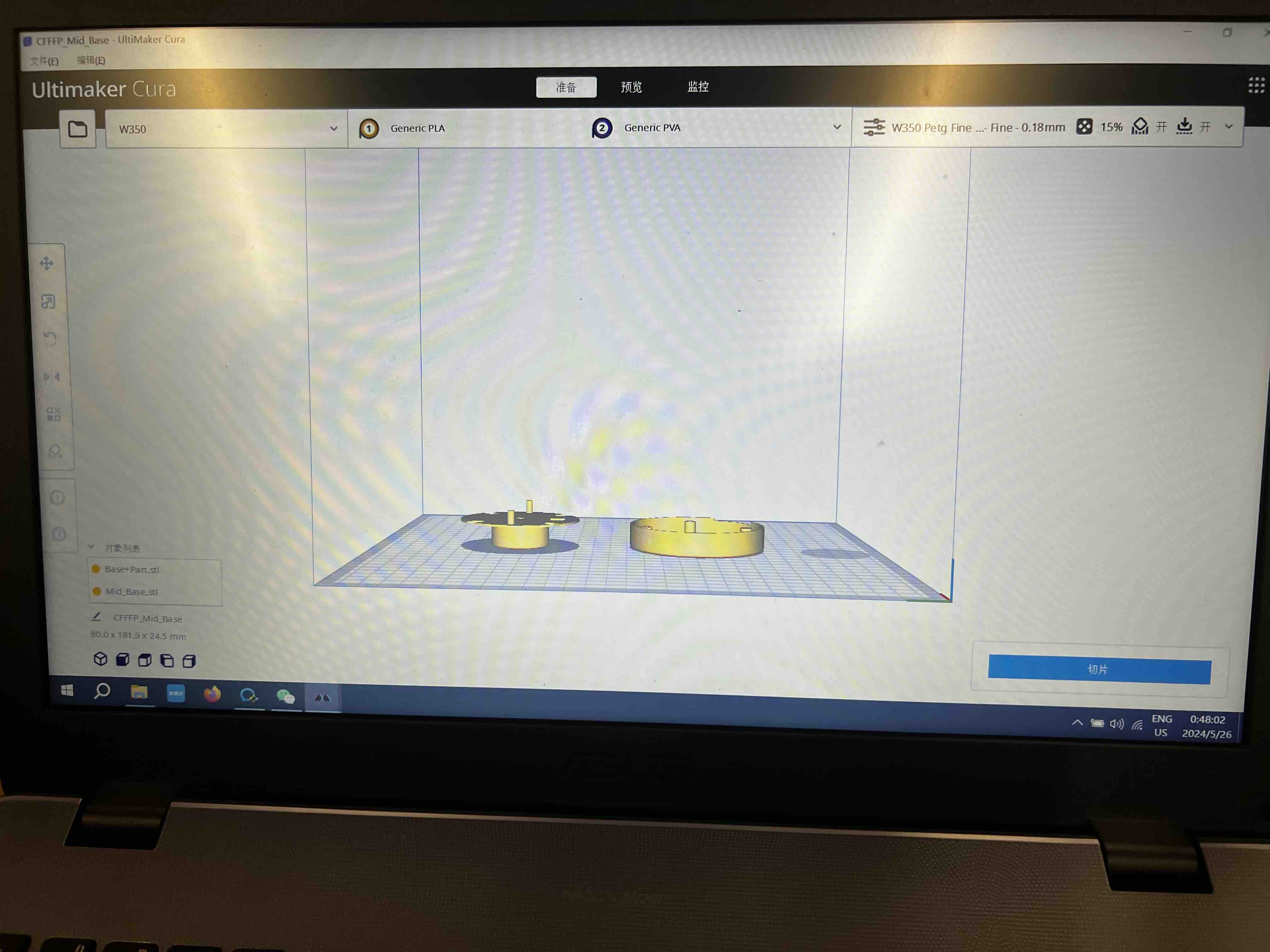
1. Manufacture them
I needed to use materials that met certain aesthetic requirements.
However,
I found that the 3D printer at Chaihuo Node was not sufficient to achieve the high-quality manufacturing needed.
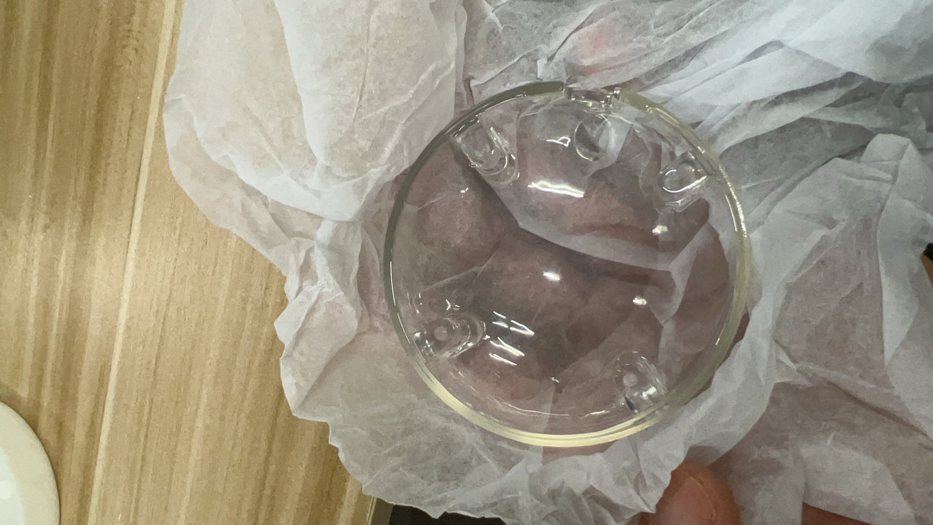
I wanted the transparent top cover and the base to have a more attractive appearance,
so I chose to find a 3D printing service provider for manufacturing.
I printed the middle support parts myself and attempted the assembly.
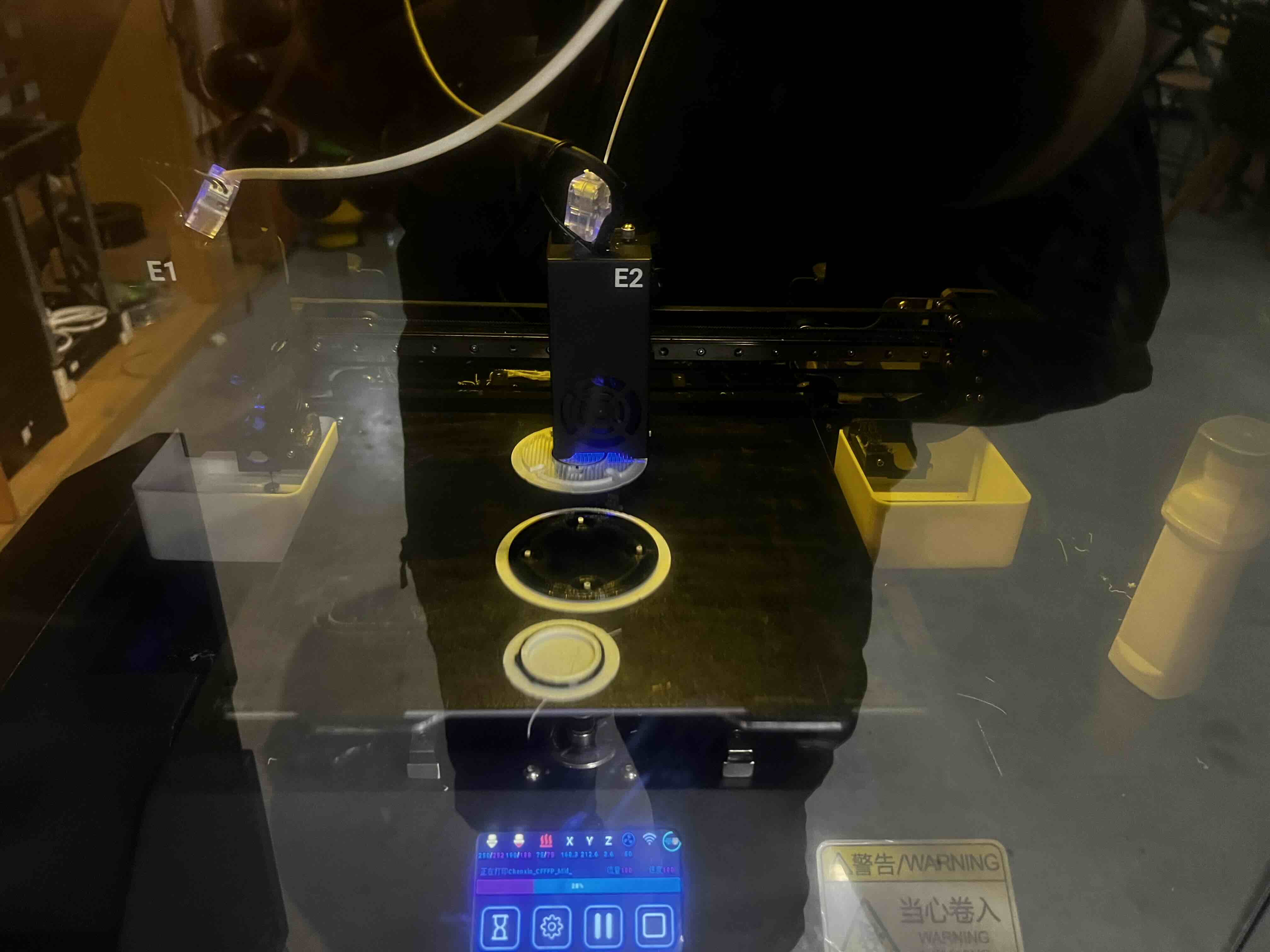
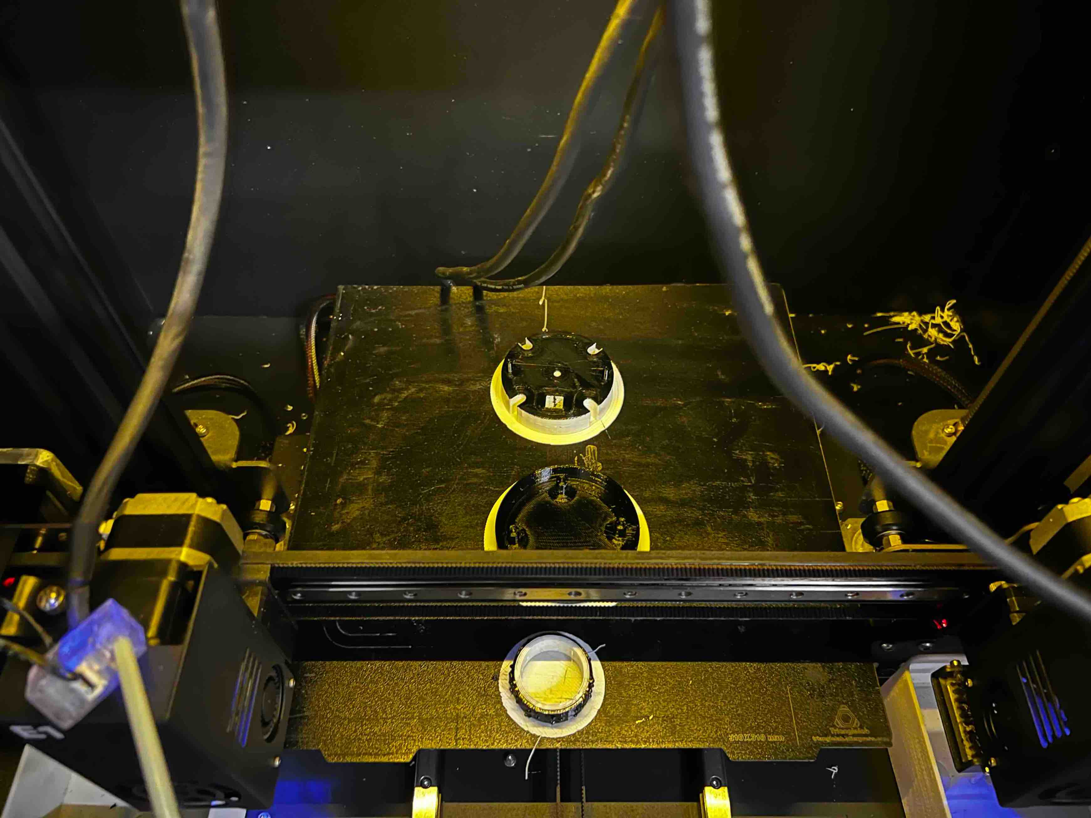

the support parts,
and the base together,
to confirm if they can be assembled properly.
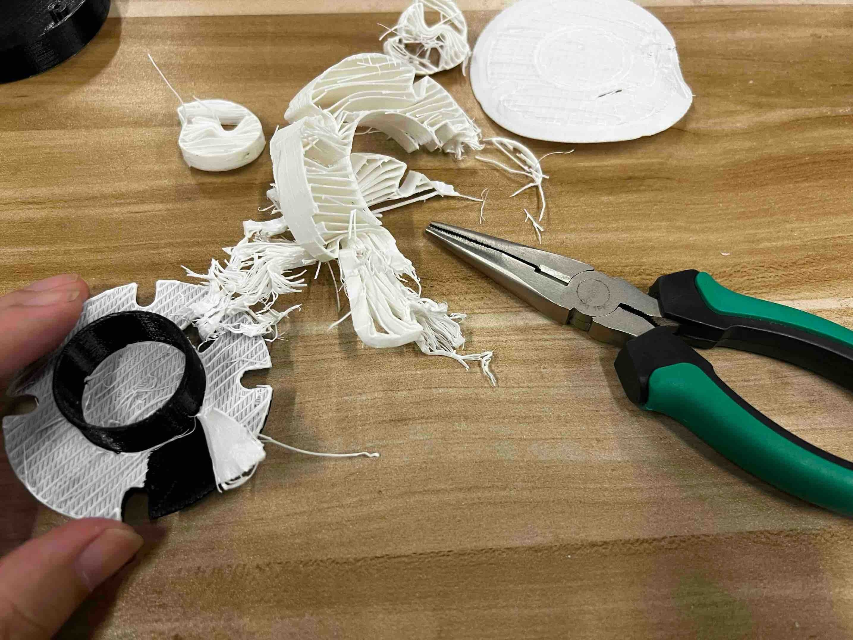
However,
I found that the middle support parts I printed at Chaihuo had significant errors.
Therefore,
I had to trim the interfaces of the parts with other tools,
and finally managed to install them.
********Final adjust Update*********
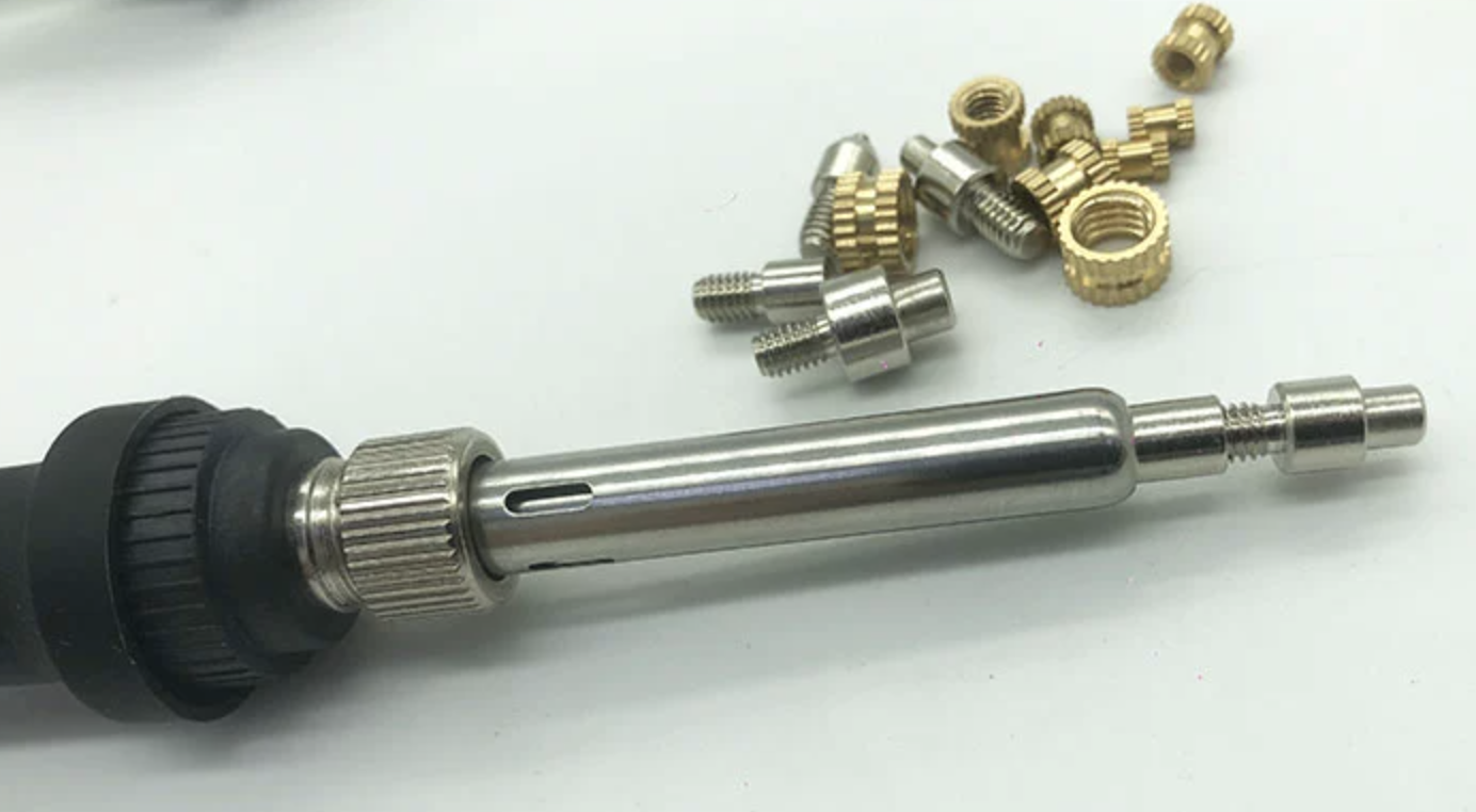
3.Which tools and parts do I need?
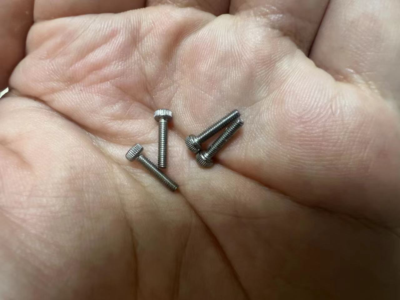
I will be using a hot melt gun, hot melt nuts, and corresponding screws for my project.
Importantly, after completing the design of the holes in the casing, the most critical point is to ensure that the screws are not misaligned.
If they are installed incorrectly, the entire assembly would be compromised and rendered unusable.
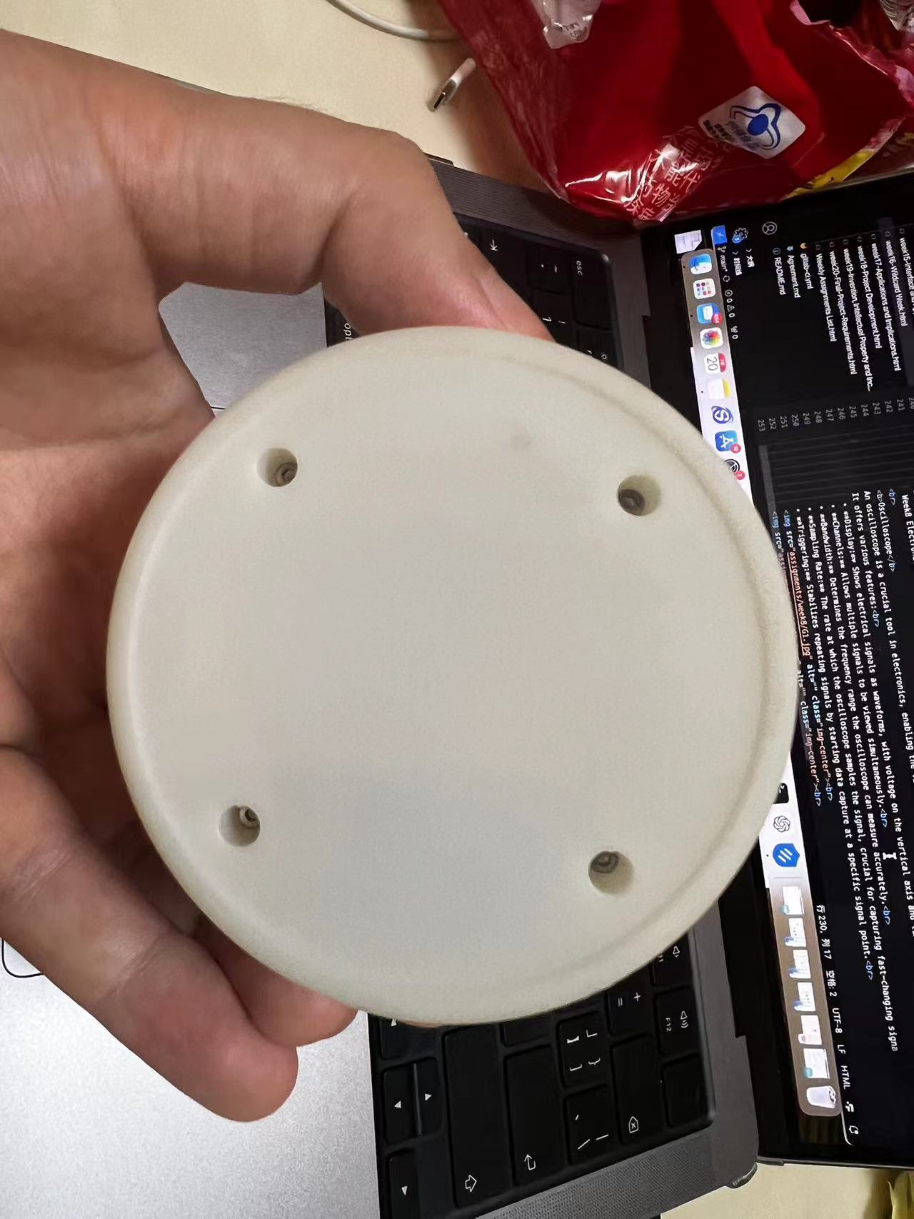
4.Manufacturing Process
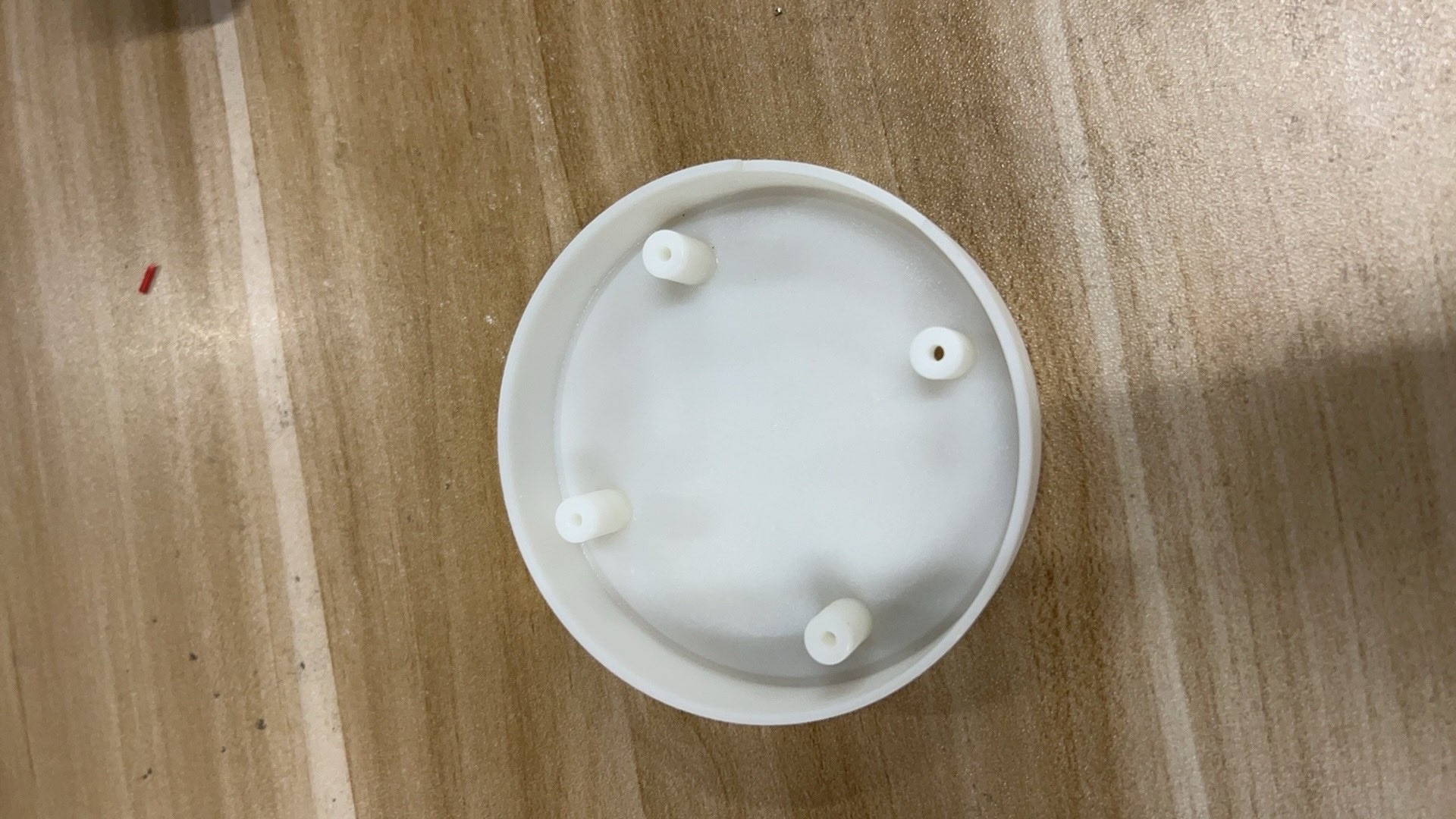
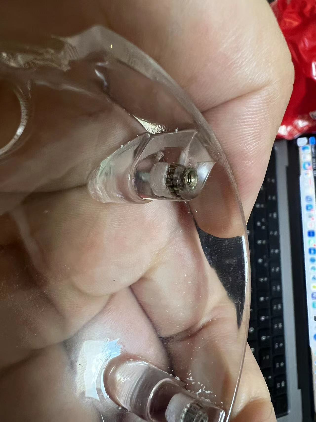
Due to the need for rapid insertion of the hot melt nuts based on the actual temperature during installation, I completed this step at home.
Unfortunately, I was unable to record the process in real-time.
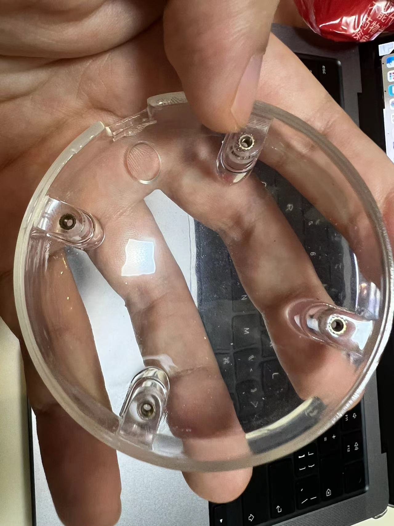
You can see the close-up of the screws after installation and the final appearance of the four screws being properly secured.
I completed this part of the work with great care.
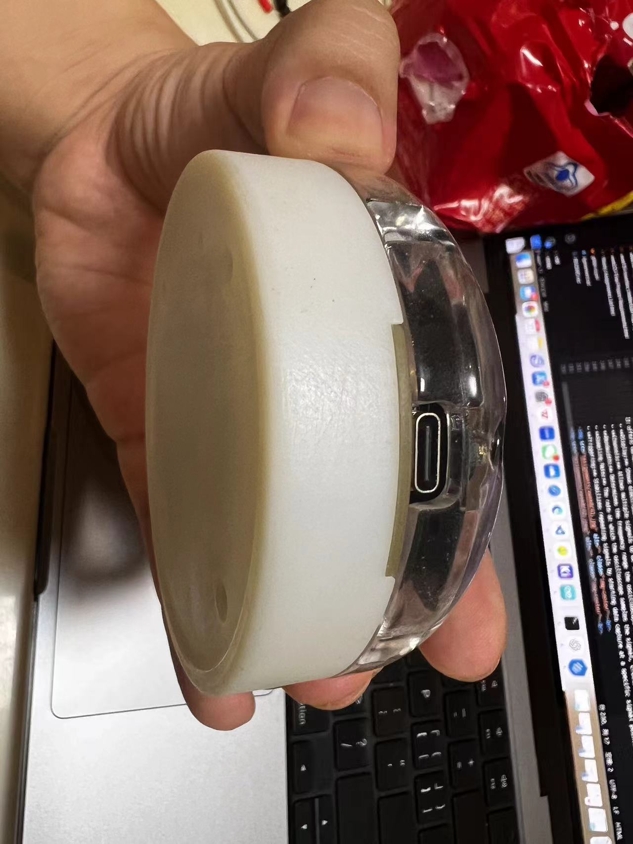
5.Assemble
I designed grooves in the transparent cover and the PCB to ensure they precisely snap into their corresponding positions. This design ensures the accuracy of the screw hole alignment.
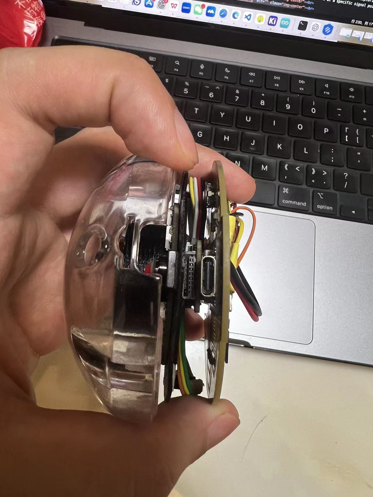
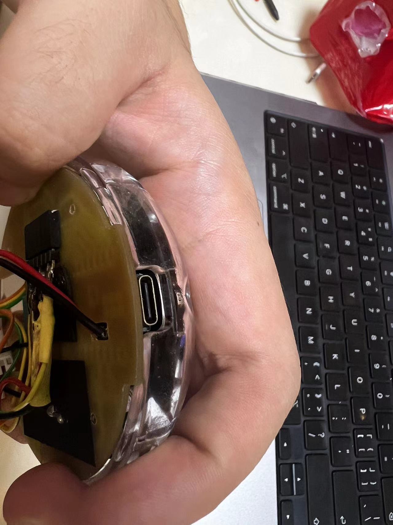
As you can see from the images, after the cover and PCB are installed, the screw holes are clear, and the nuts are visible.
Furthermore, after assembling the top and bottom covers, there is a small gap left in the middle to facilitate tightening the screws with a hex wrench.

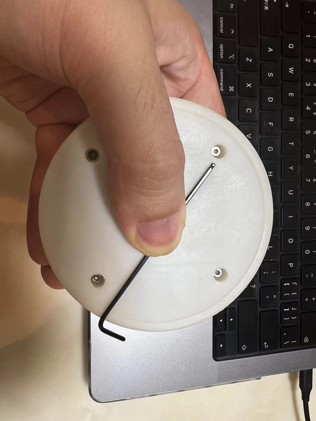
Once the screws are secured, the gap between the assembled parts is minimal. Nice!
The PCB design of the Dao Clock
Overview of the PCB design
My circuit design is divided into two main sections.
One part is the upper module used to fix 12 Neopixels, a light sensor, and a Xiao camera component.(Hereinafter referred to as “PCB_Part1”.)
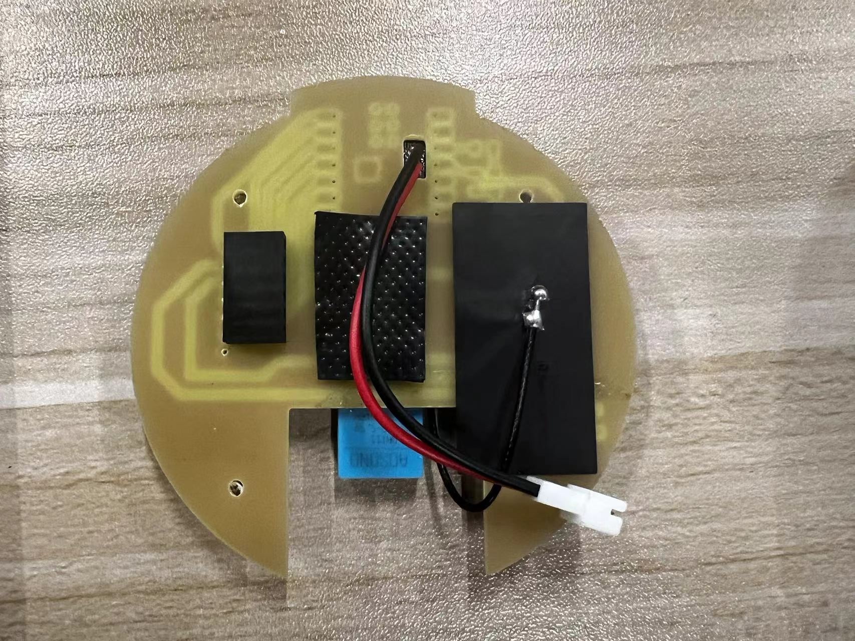
The other part is the main control circuit board, which includes the Xiao ESP32S3, interface connections, speaker, and battery connection components.(Hereinafter referred to as “PCB_Part2”.)
Before starting, I gathered the specifications and information for the sensors needed for this project.
Here is the list:
| Item Number | Description | Quantity | Price | Link |
|---|---|---|---|---|
| 1 | DHT11 - Temperature and Humidity Sensor Module | 1 | $5.99 | Buy Here |
| 2 | R-1206 - 4.99K - SMD | 1 | $0.014 | Buy Here (Yageo RT0402) |
| 3 | R-1206 - 1K - SMD Resistor | 1 | $0.00606 each for 125,000 units | Buy from DigiKey |
| 4 | R-1206 - 499R - SMD Resistor | 1 | Starting at $0.10 each | Buy from Mouser |
| 5 | C-1206 - 100nF - SMD Capacitor | 1 | $0.26 | Buy from RS Online |
| 6 | Switch - SW2 - B3SN-3112P - OMRON | 1 | $0.85 each | Buy from DigiKey |
| 7 | NeoPixel x 12 - 5mm | 1 | $4.95 for 5 pack | Buy Here (Adafruit) |
| 8 | LED-1206 GREEN - SMD | 1 | $0.382 each, less for larger quantities | Buy Here (Newark) |
| 9 | Seeed-Xiao - ESP32 - S3 - Sense | 1 | $13.99 | Buy Here |
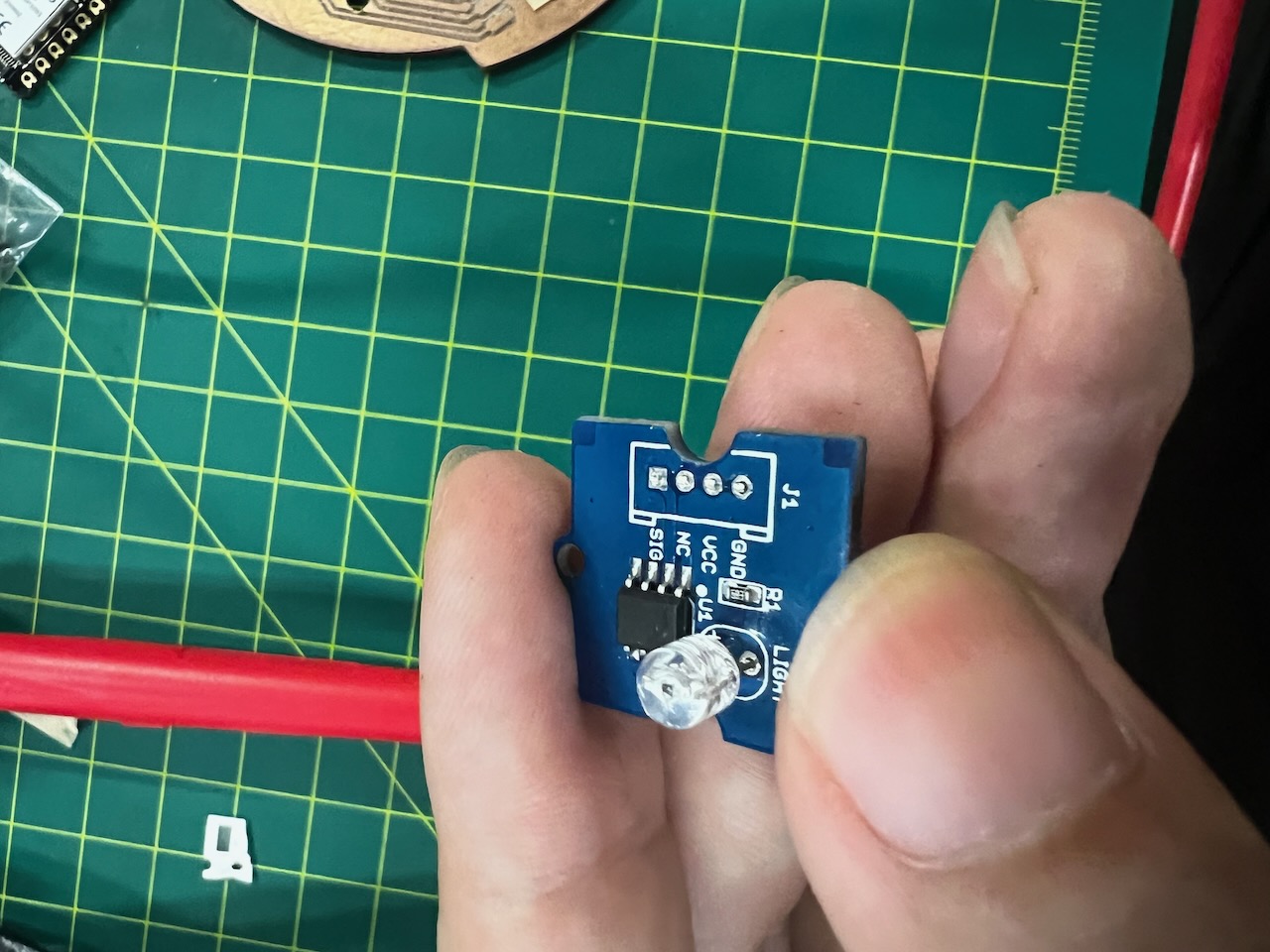
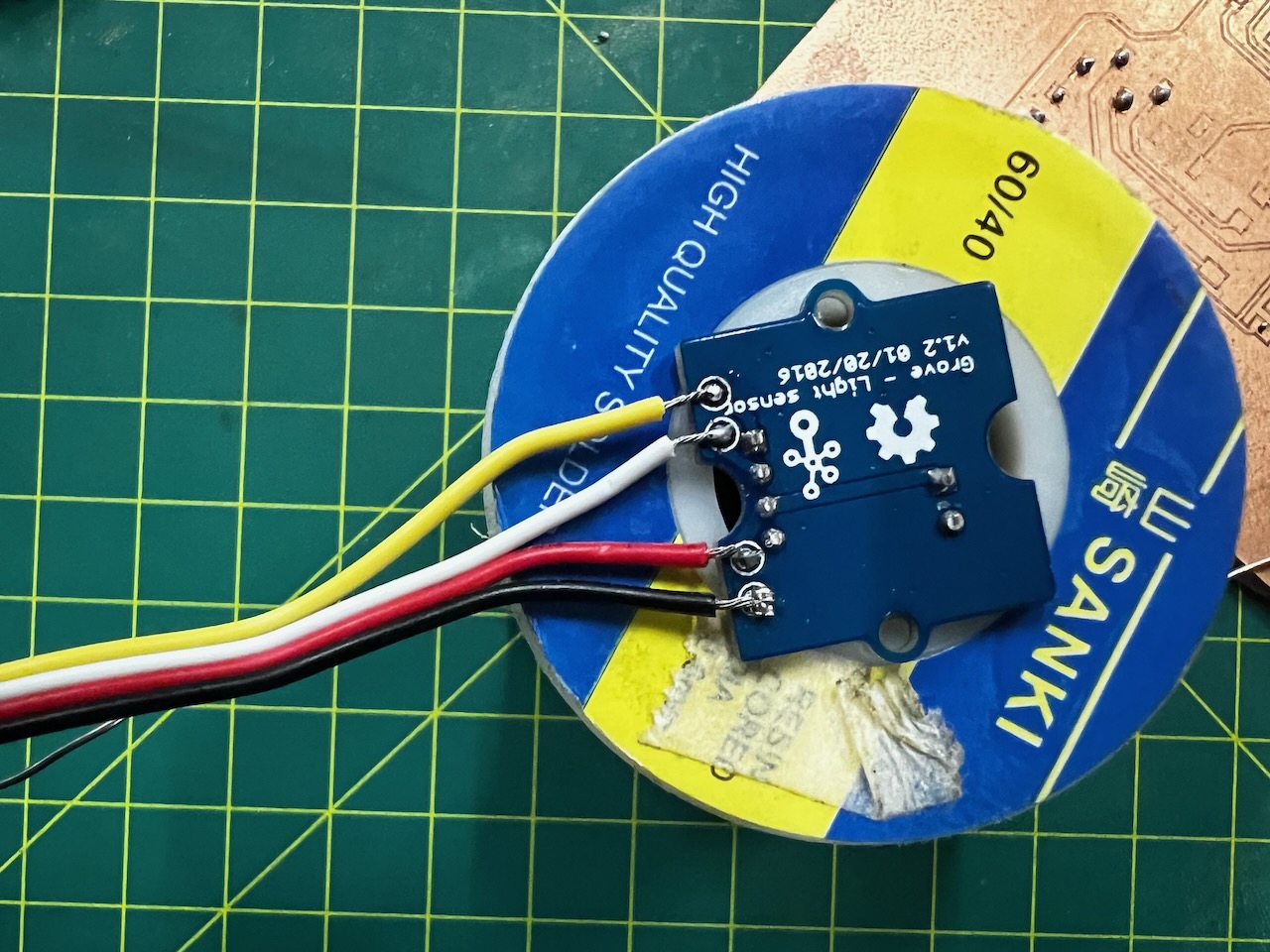
| 10 | Grove - Light Sensor v1.2 | 1 | $3.90 each | Buy from Seeed Studio |
| 11 | Grove - MP3 Speaker | 1 | $6.90 each | Buy from Seeed Studio |
PS:The overall PCB design took me a lot of time, and due to the design difficulty, I had to adjust the corresponding 3D appearance design scheme.
The modification process is as follows:
but I found that due to the small size of the PCB, it couldn't be achieved through CNC engraving.
Therefore, I changed the design plan.
the flashing of the Neopixels would interfere with the normal operation of the light sensor, so I changed the scheme.
I found that the sensor layout direction was wrong, causing the DHT11 to be damaged.
I redesigned a version of the PCB.
1.Design and Manufacturing of PCB_Part1
First design plan:Discarded
My circuit design is divided into two main sections.
One part is the upper module used to fix 12 Neopixels, a light sensor, and a Xiao camera component.
The other part is the main control circuit board, which includes the Xiao ESP32S3, interface connections, speaker, and battery connection components.
Here is the PCB_Part1 design:
Suddenly,I discovered a critical issue with this design,
I could not achieve processing with a small CNC,
because the traces had to be very thin.
Our CNC's engraving bit can only achieve a size of 0.4mm.
I consulted with Mentor Salman,
and his final suggestion was to use pre-made Neopixels components with 12 LEDs.
Therefore,I readjusted the overall design plan.
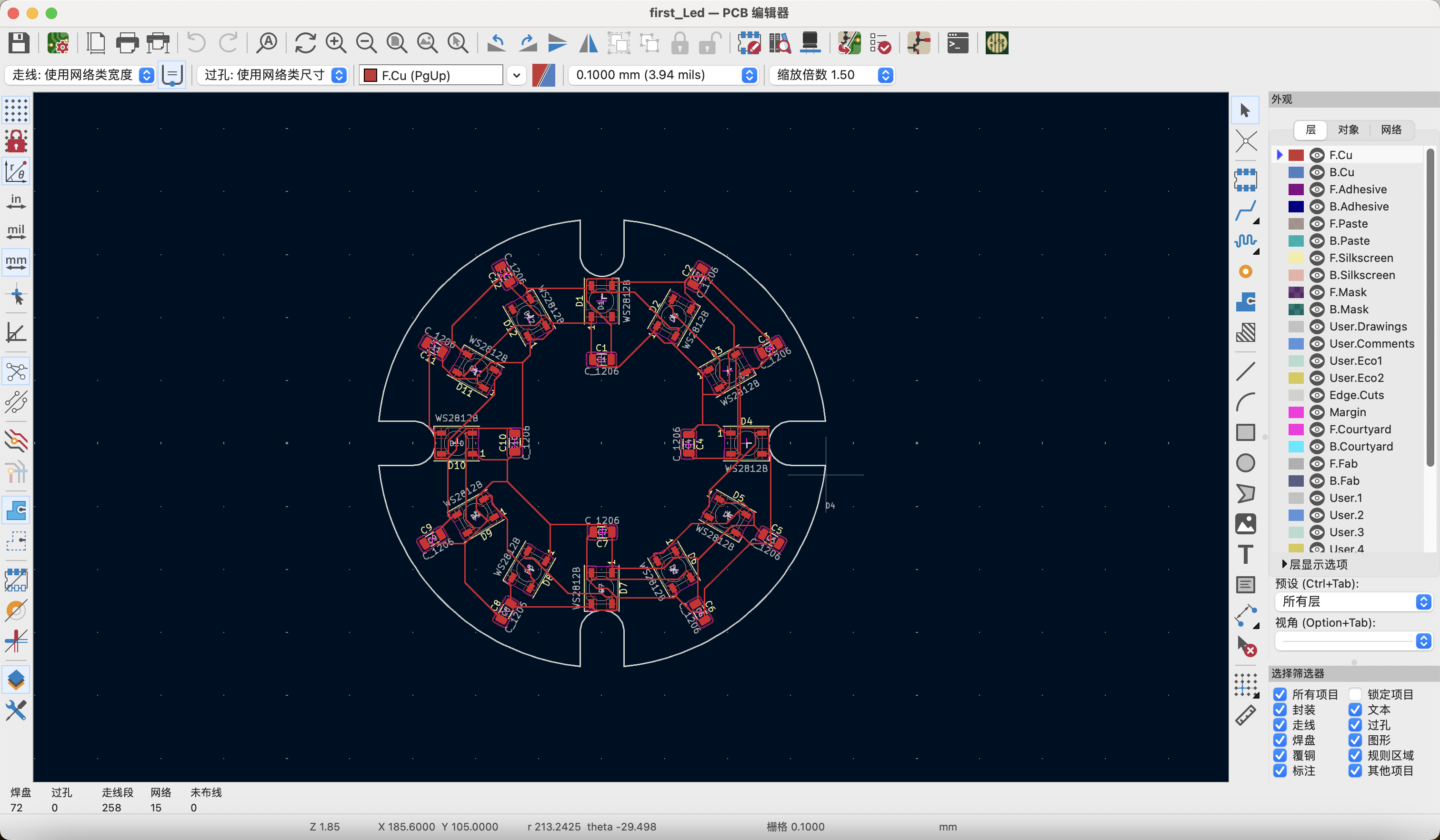
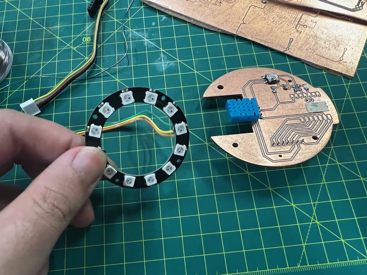
Successful New design:Jumpers and structural support for sensors.
Ultimately,I used jumpers to connect the necessary sensor components by soldering them together.
I used the support structure to reasonably arrange the sensors on it as much as possible,forming a new assembly.
In designing the output involving the NeoPixel ring, I initially used my own PCB design. However, I encountered significant issues with trace routing because we used 12 NeoPixels, and each NeoPixel, according to the documentation, required the addition of a capacitor. This made it challenging to carve the PCB using CNC due to the limitations imposed by the trace width.
On the advice of my instructor Salman, he provided me with a pre-made 12 NeoPixel ring, allowing me to use a ready-made module to complete my output design.
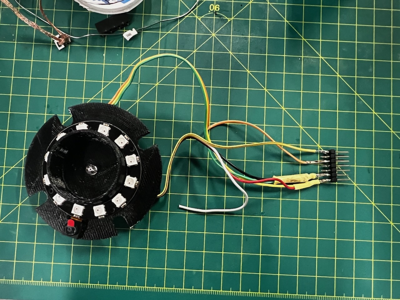
After using the new ring, I adjusted my design plan. The original plan was to design another PCB to accommodate 12 NeoPixels.
However, after switching to the 12 NeoPixel ring method, I redesigned the support structure to accommodate this component.
By using a multimeter to test the connectivity of each component,
I ensured that there were no short circuit issues.
Final PCB_Part1 design is as follows:
2.Design and Manufacturing of PCB_Part2_Main Control Circuit Board
First design plan:Discarded
When I completed my first PCB design, I was the fastest progressing member in our group.
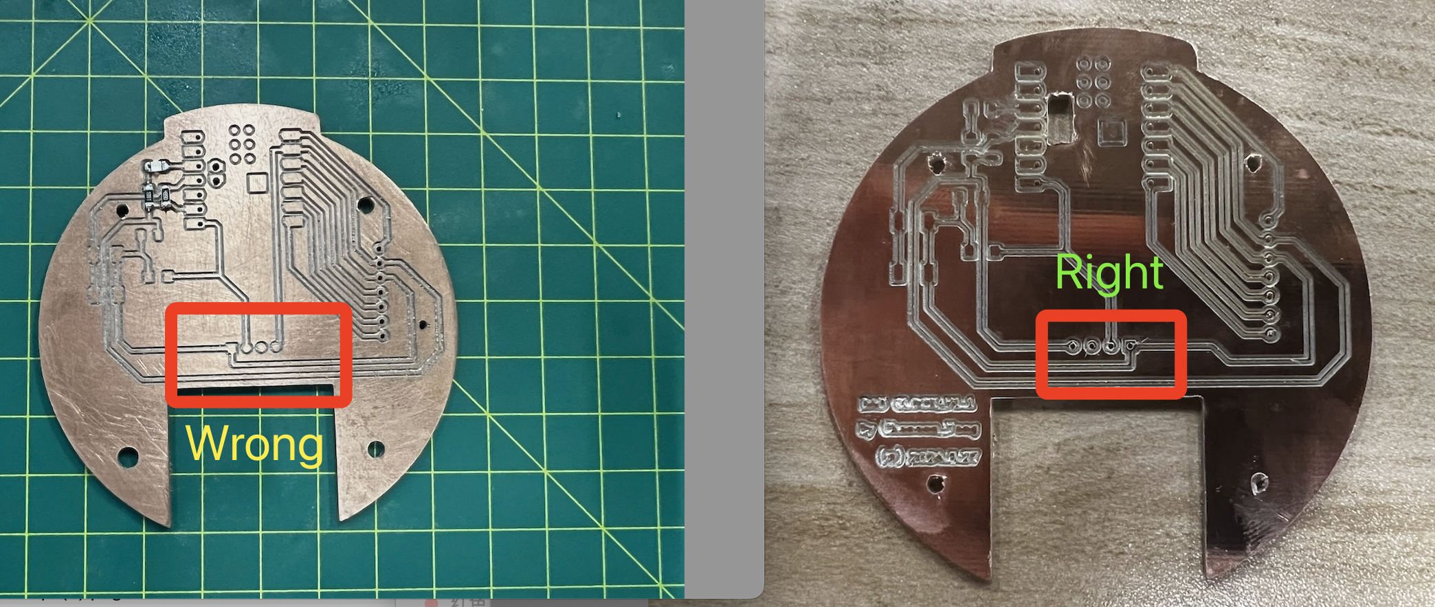
However, during the subsequent program testing, I found that the DHT11 was not functioning properly, and I smelled something burning.
I realized there must have been a short circuit somewhere.
After attempting to troubleshoot many times and burning out another DHT11 sensor, I discovered that a flaw in the circuit board design had caused me to connect the pins incorrectly, thereby damaging the DHT11 component.
The circuit board I showed earlier is the correctly adjusted final design.
Now, I'm also sharing the failed version.
This reminds me to carefully and meticulously review the component datasheets to ensure correct installation.
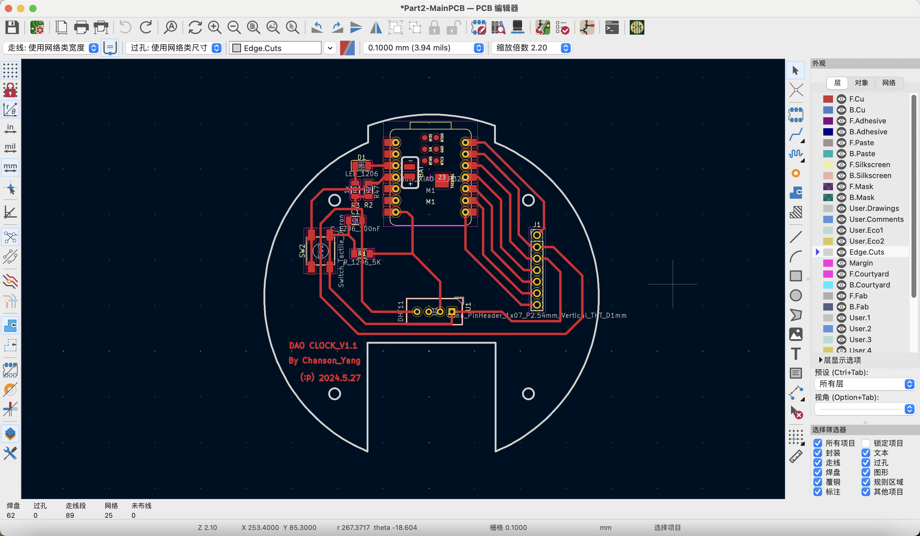
Final design plan
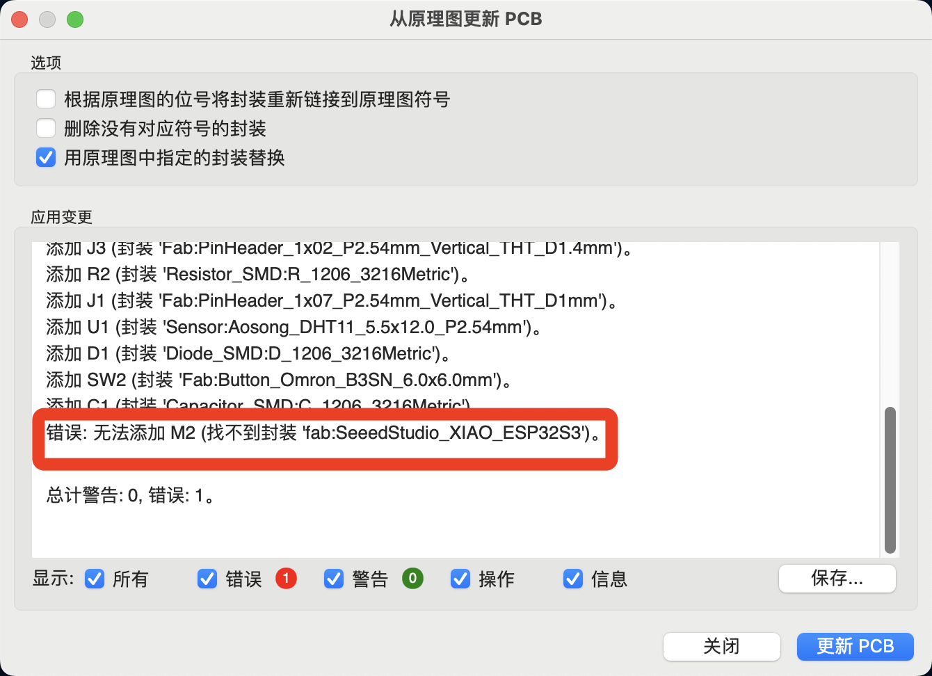
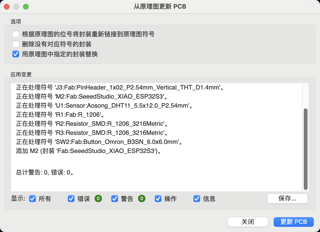
Update the PCB from the schematic.
During the conversion from schematic to PCB, a minor error occurred: I discovered that the Xiao did not have a corresponding footprint.Consequently, I went into the component editor to match the appropriate component again.
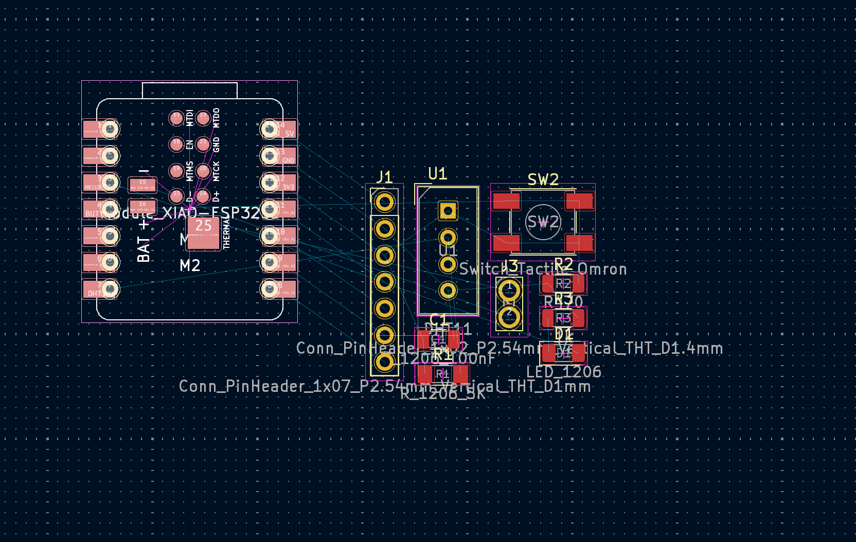
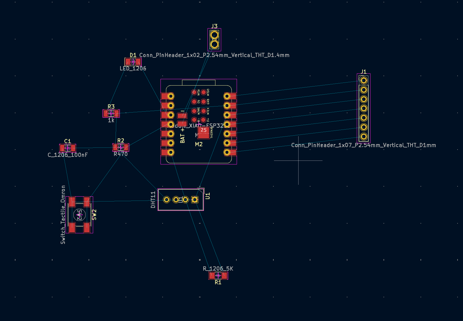
PCB Component Layout
I designed the PCB layout using the following guidelines:It also insteresting to see the final layout of the PCB.
First step is to place the components in a logical and intuitive manner.
I will first separate them to minimize the crossing of wires.
PCB Board Outline Design
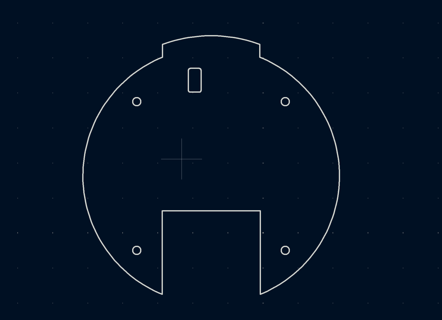
However, routing and component placement indeed require certain skills; this took up much of my time, to the extent that I kept working on it and failed to document many steps.
Ultimately, I achieved the design I wanted.
The PCB Manufacturing
From Gerber to G-Code
The knowledge used in this part is the same as that in Week 4.
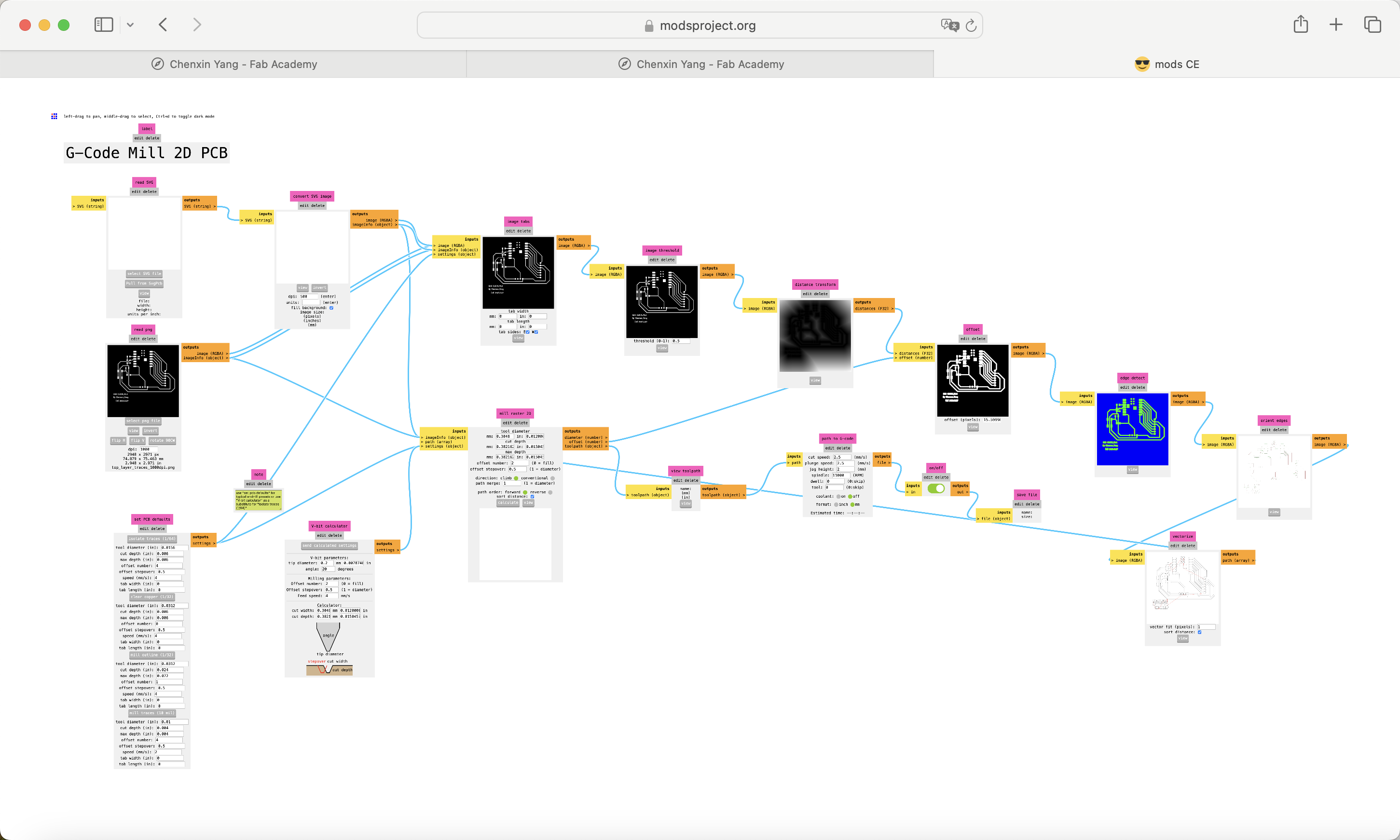
Converting from Gerber files to G-code files involves two steps:
1. Convert the Gerber files into recognizable PCB photoprint images.
2. Generate G-code files from the photoprint images.
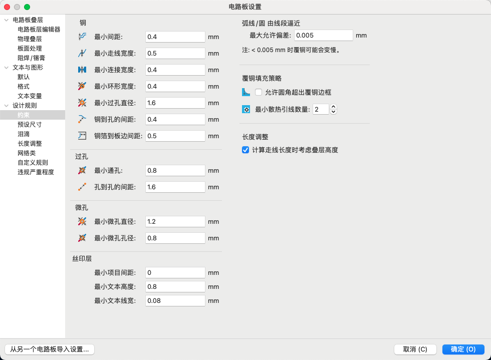
Please remember to adjust the PCB design rules, as we are using CNC machining for the PCB.
Pay attention to the minimum precision possible with CNC machining.
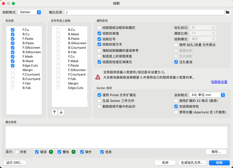
OK!We can get the manufacturing files.
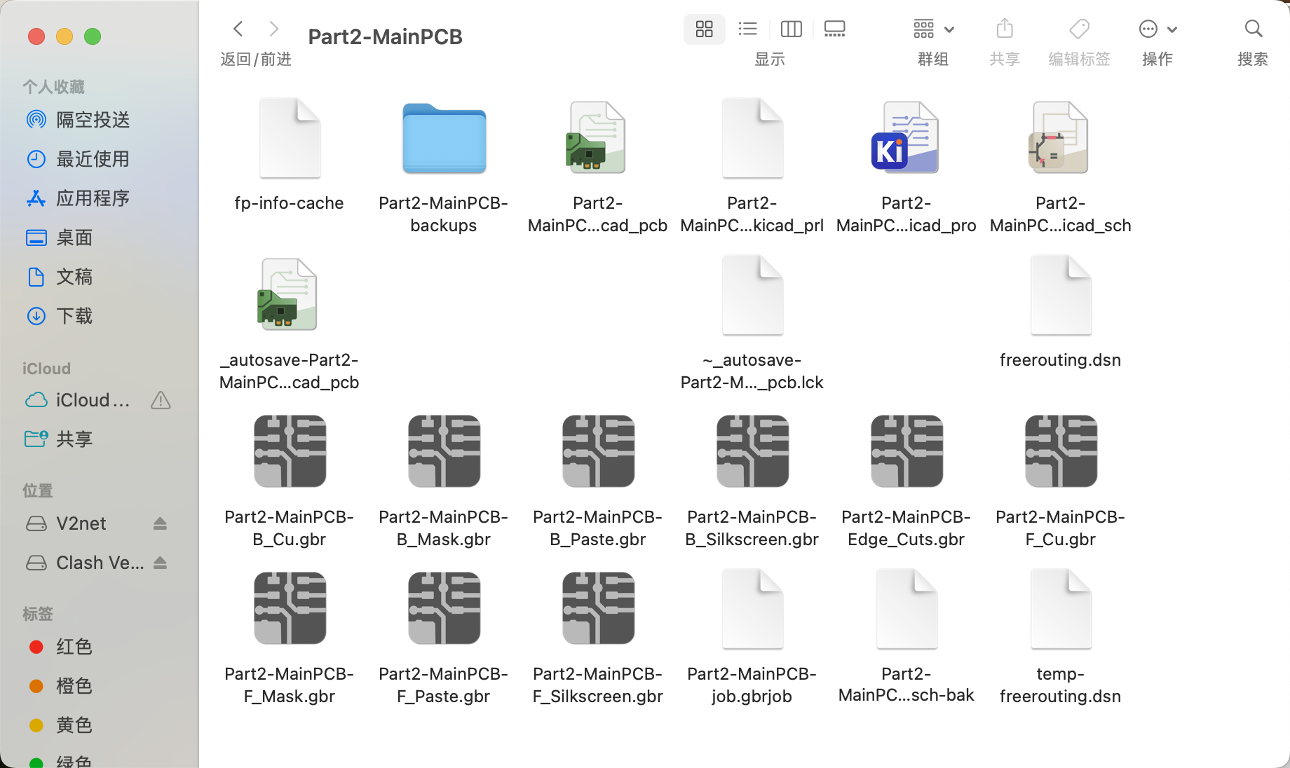
Then upload the Gerber files to the online tool Gerber2PNG to generate the PCB photoprint images.

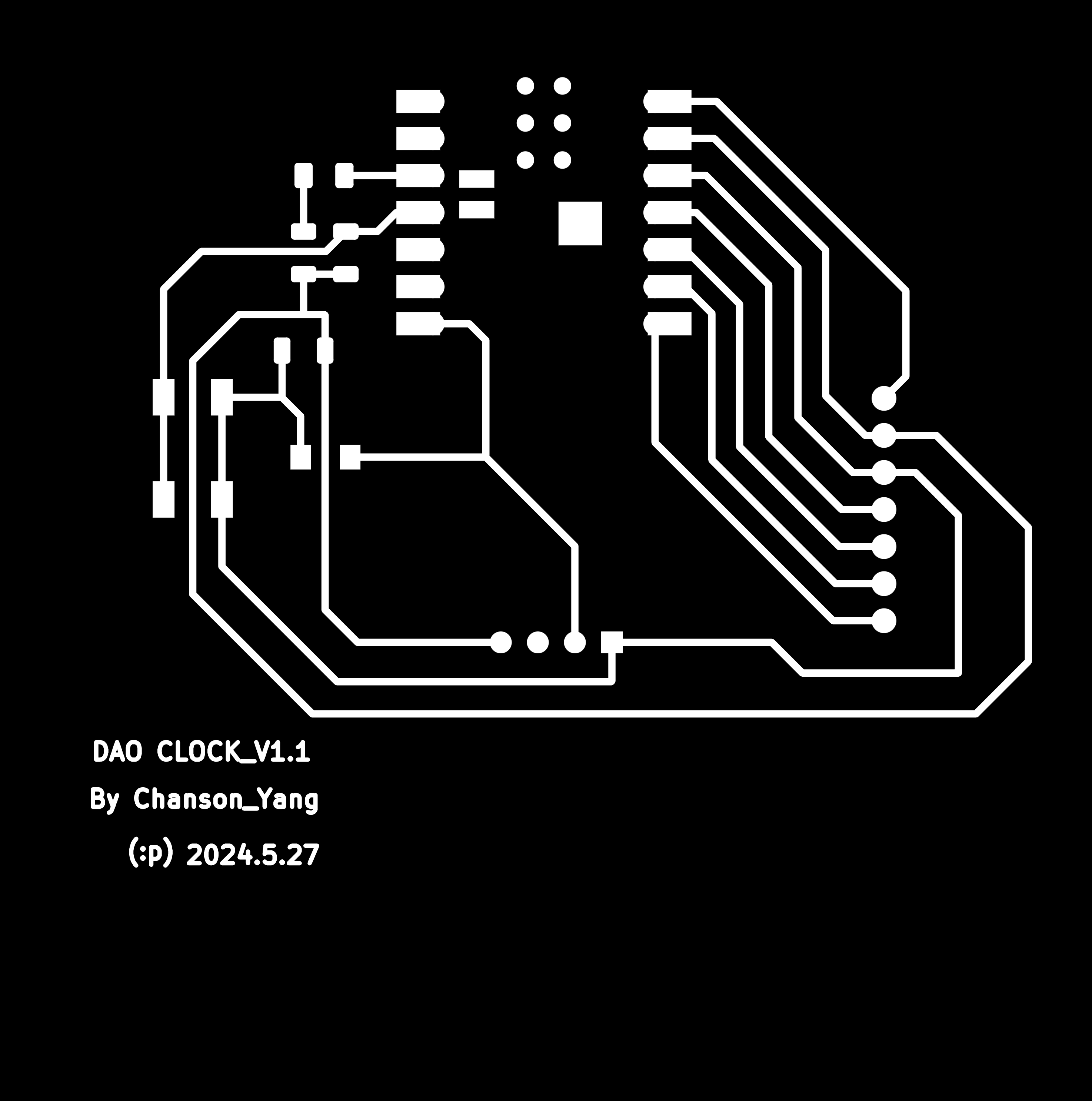
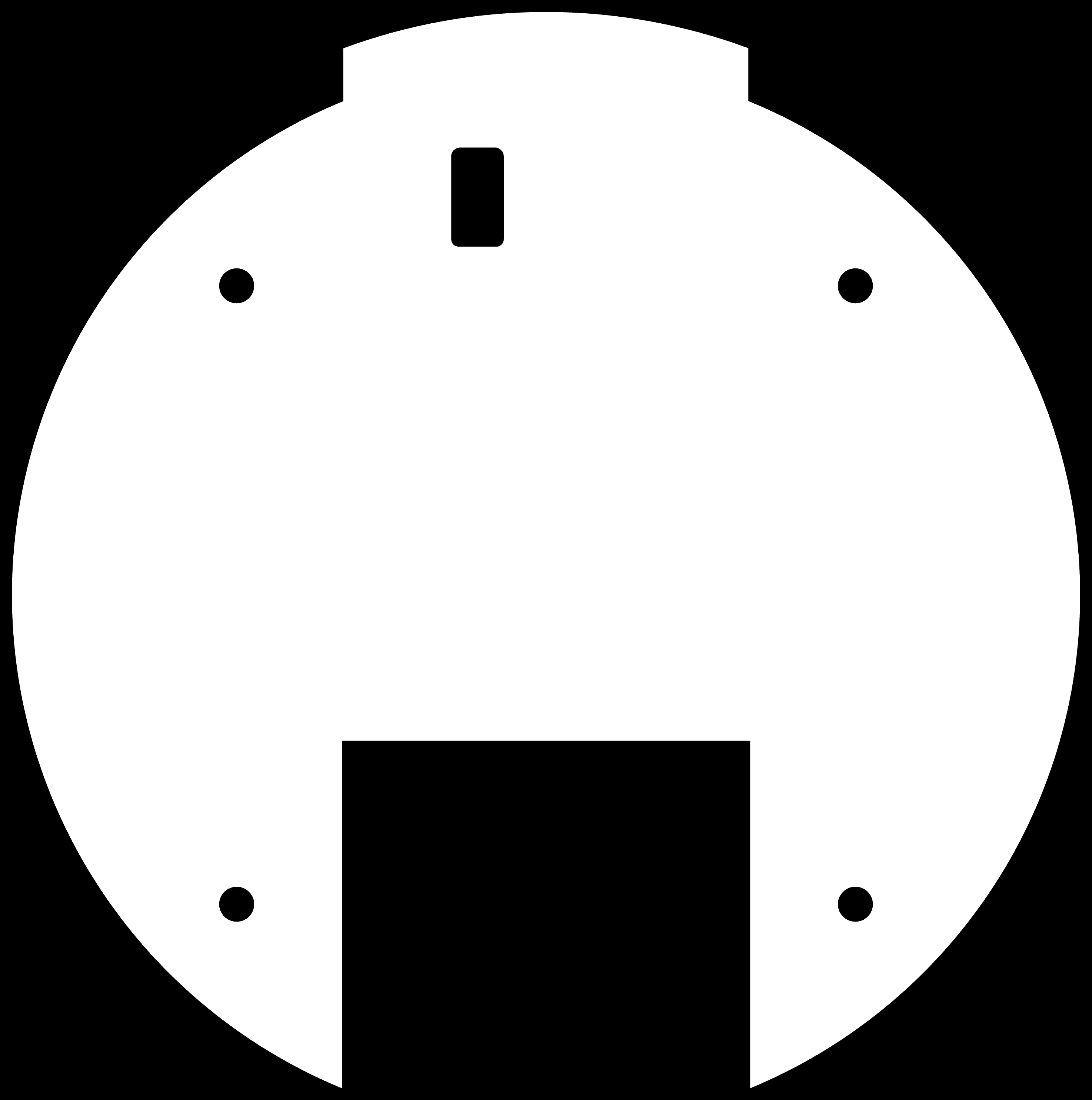
We need to get 3 images: traces, outline, and Drill.
PCB Photoprint images:
Traces:
Outline:
Drills:
.png)
 Special note:
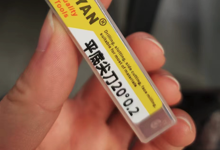
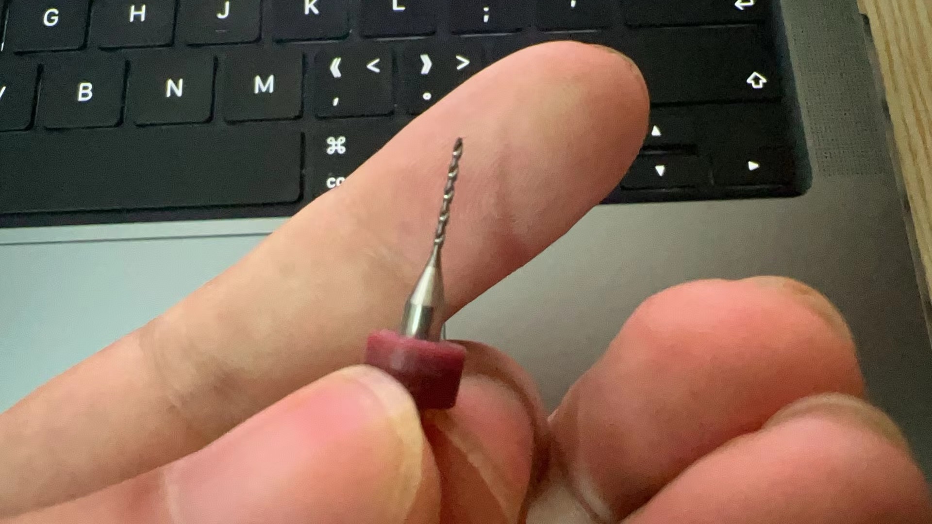
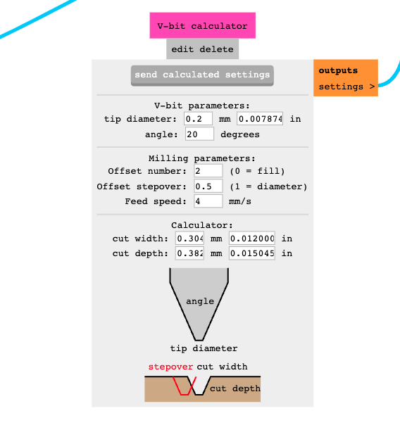
• Before setting up the machining files, please pay attention to the parameters of the engraving and drilling tools being used.
engraving tool: tip diameter--0.2mm Angle--20°
drilling tool: 0.8mm
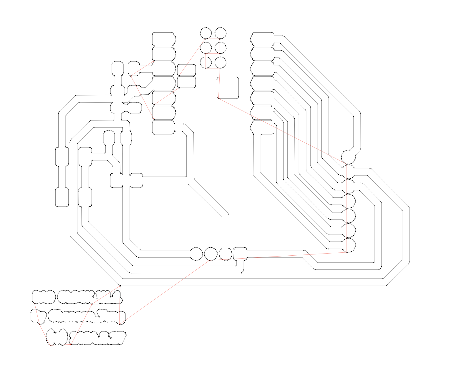
Ultimately, we can obtain a preview of the G-code file.
Machining the PCB and checking the Circuit
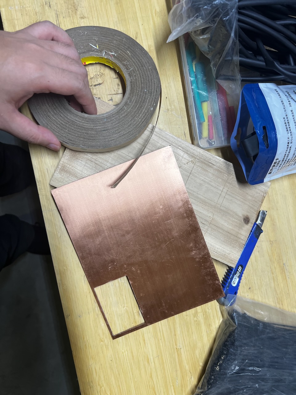
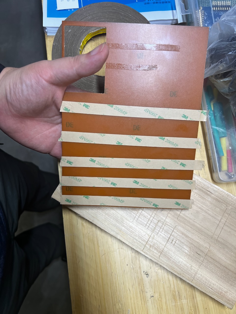
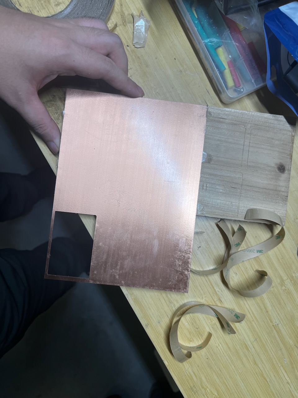
• Material Fixing: Use double-sided tape or a vise to secure the PCB material to be processed.
• Tool Loading: Choose appropriate V-bits or drills, mount them on the spindle, and lock them in place using the spindle wrench.
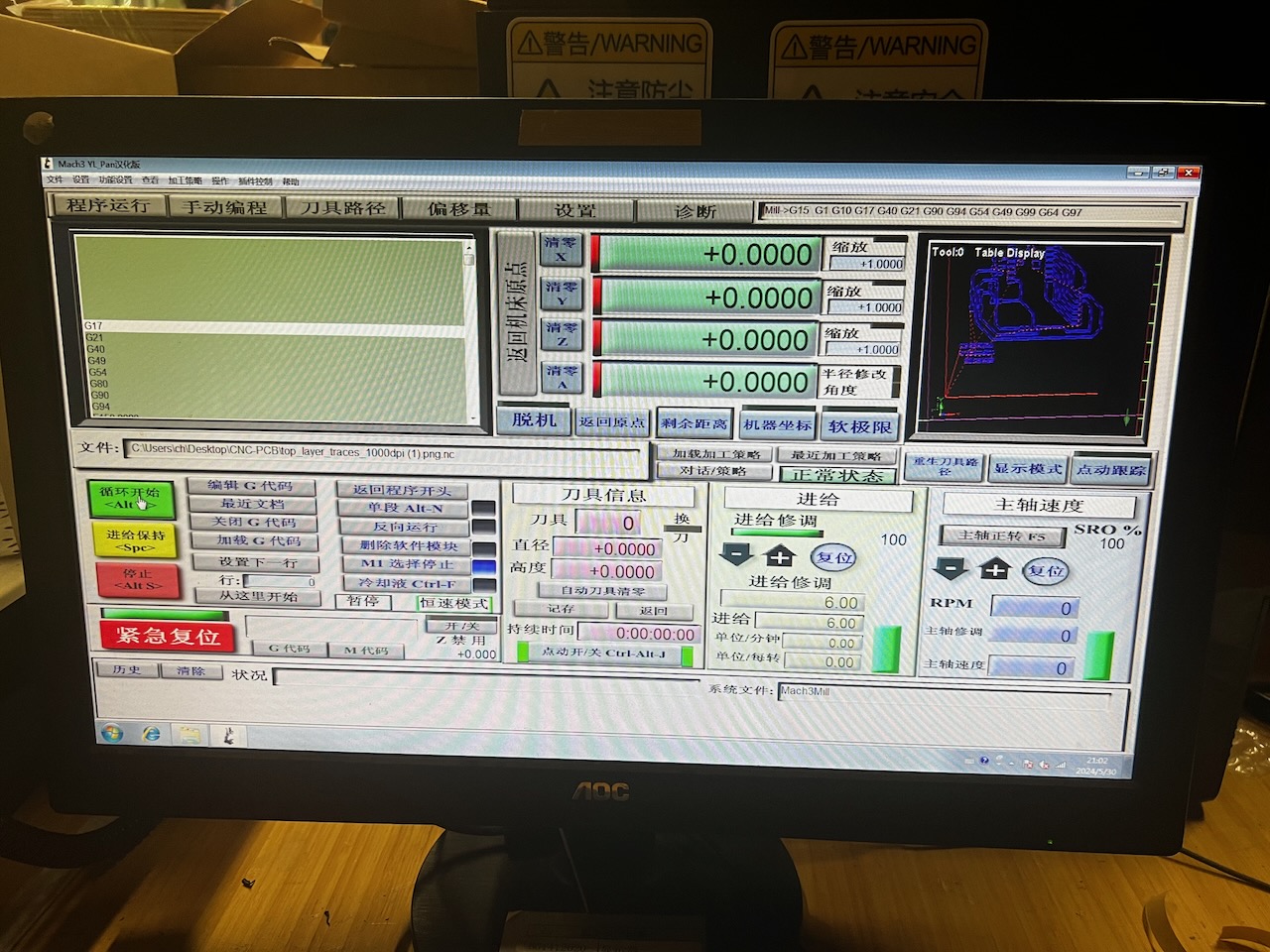
• Equipment Initialization: Use Mach3 software to power on the machine, clear alarms, and set the tool’s starting position.
• G-code Loading: Load G-code into Mach3, make final settings before machining, such as adjusting spindle speed and feed rate.
• Start Machining: Start the machine to begin processing, adjust feed rates as necessary and check the quality of machining.

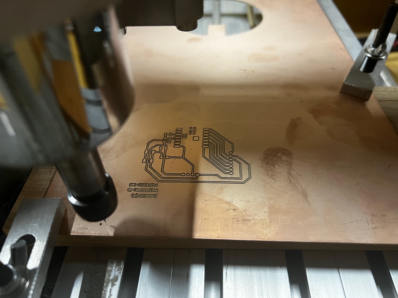

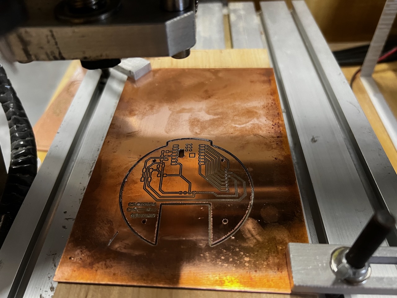
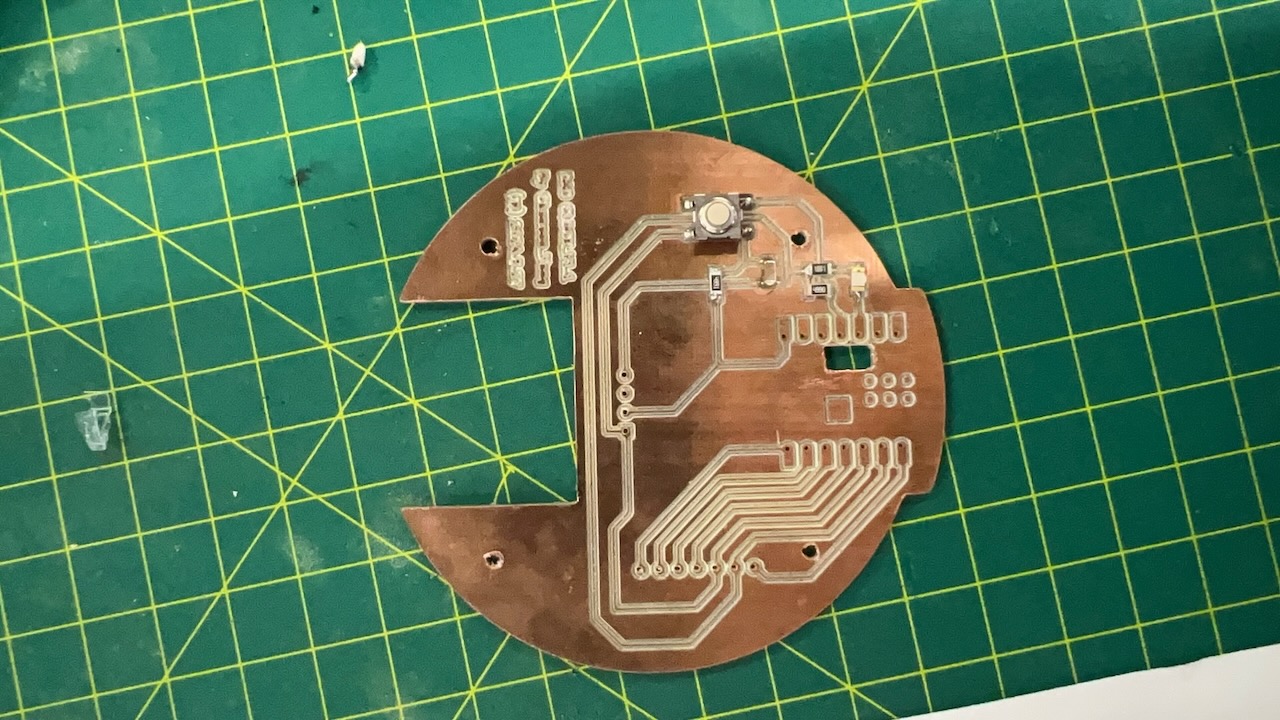
Finally, we can see the finished PCB.

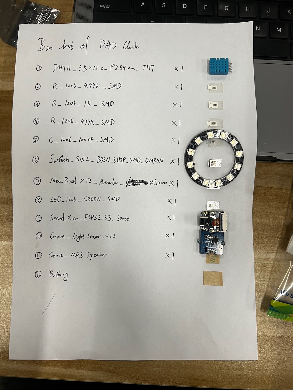
Make the BOM for Dao Clock PCB
After completing the PCB machining, I used a multimeter to test the connectivity of the PCB circuits to ensure there were no short circuits.
The specific method involved using the circuit connectivity test function of the multimeter, testing all the wires one by one with the positive and negative probes.
Here is the BOM (Bill of Materials) for Dao Clock.
I found each required component from the component storage area one by one, organized them together, and made a list.
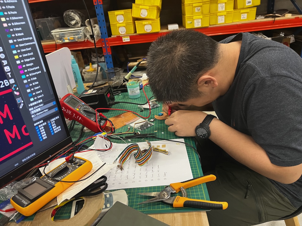
Solder components onto the PCB
After completing the soldering of the main components, I began soldering the Xiao ESP32-S3.
Below is the pinout manual for the Xiao ESP32-S3.
Also, be sure to place an insulating sticker at the power pin location to prevent short circuits.
The dao clock PCB is now soldering completed.
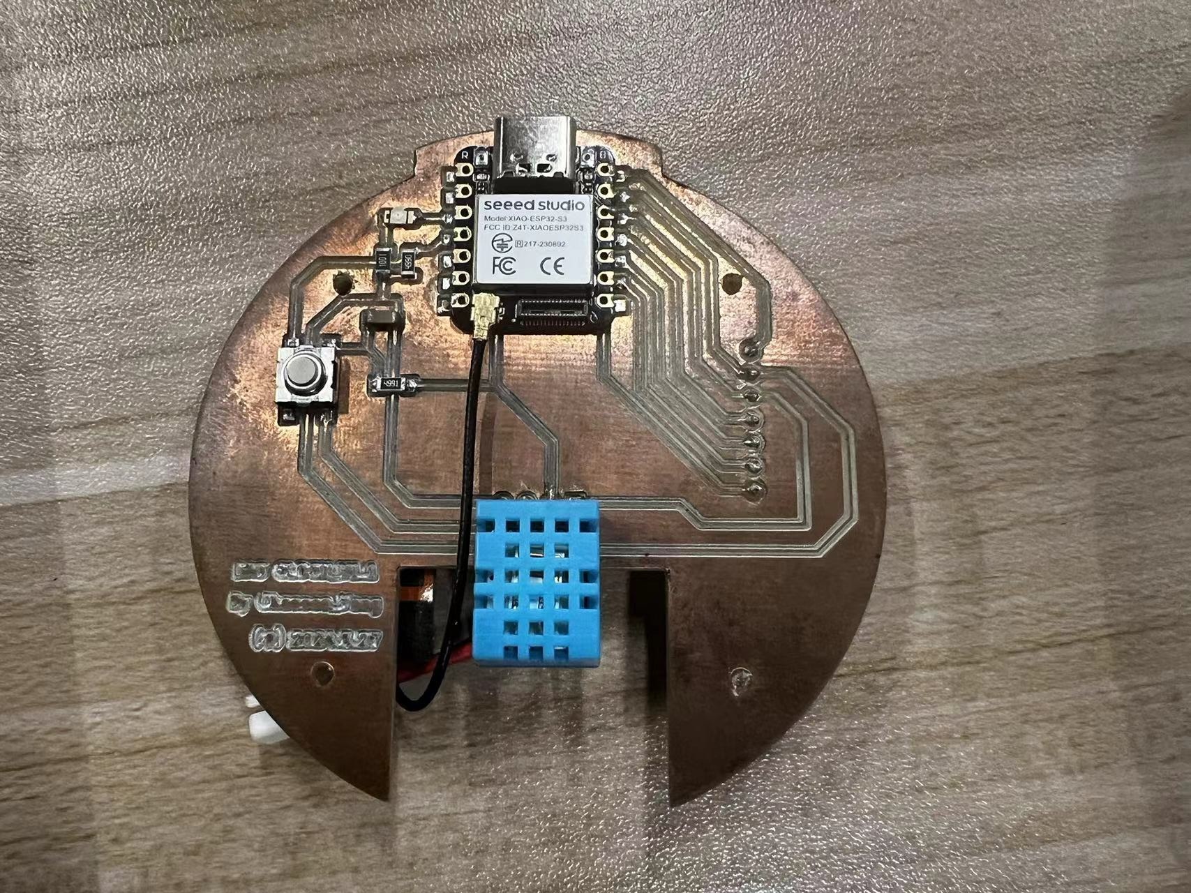
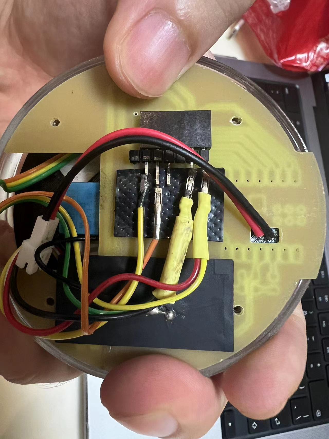
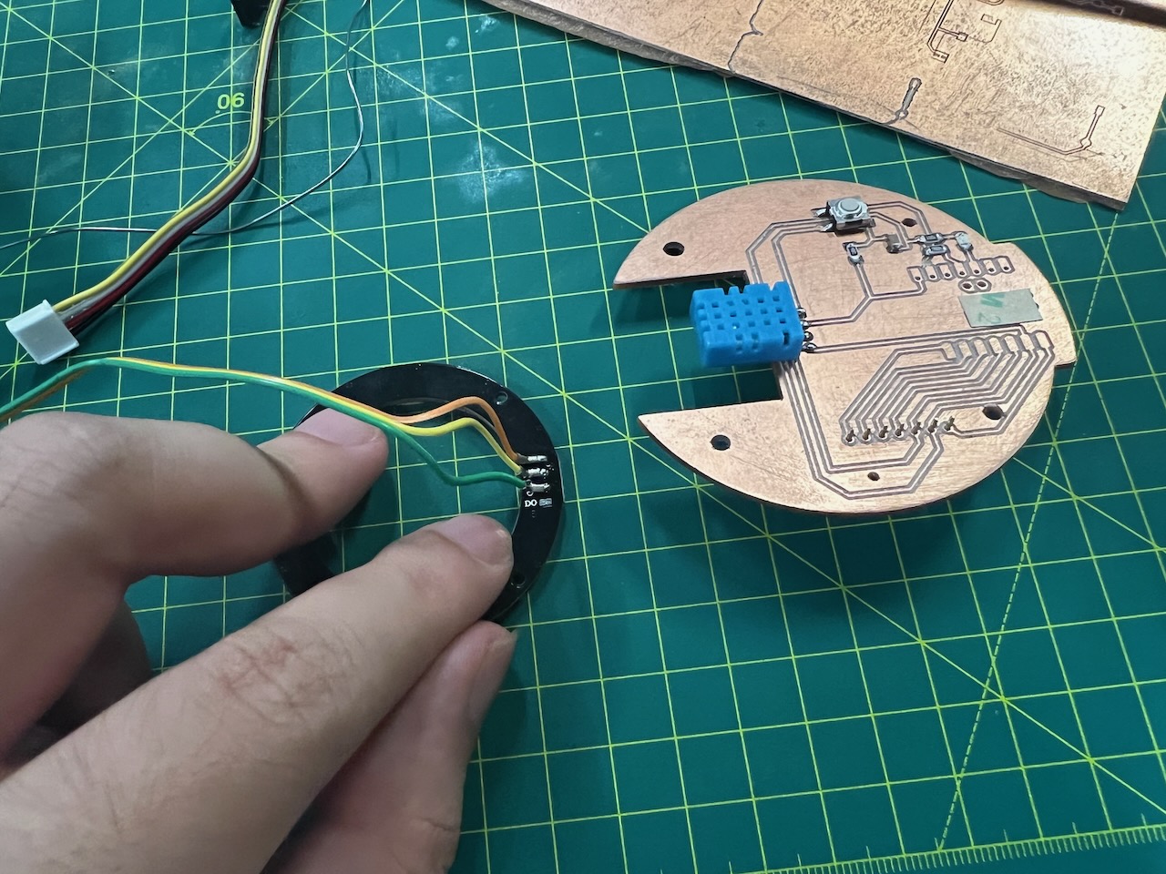
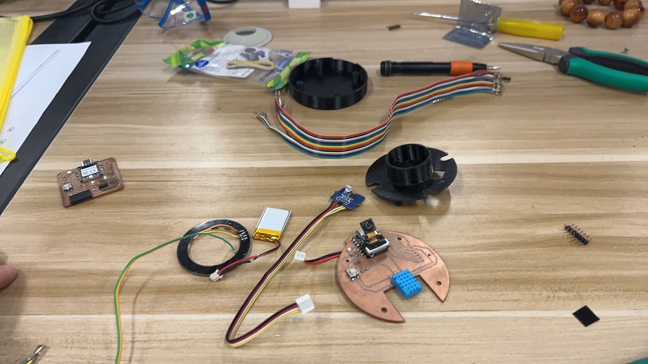
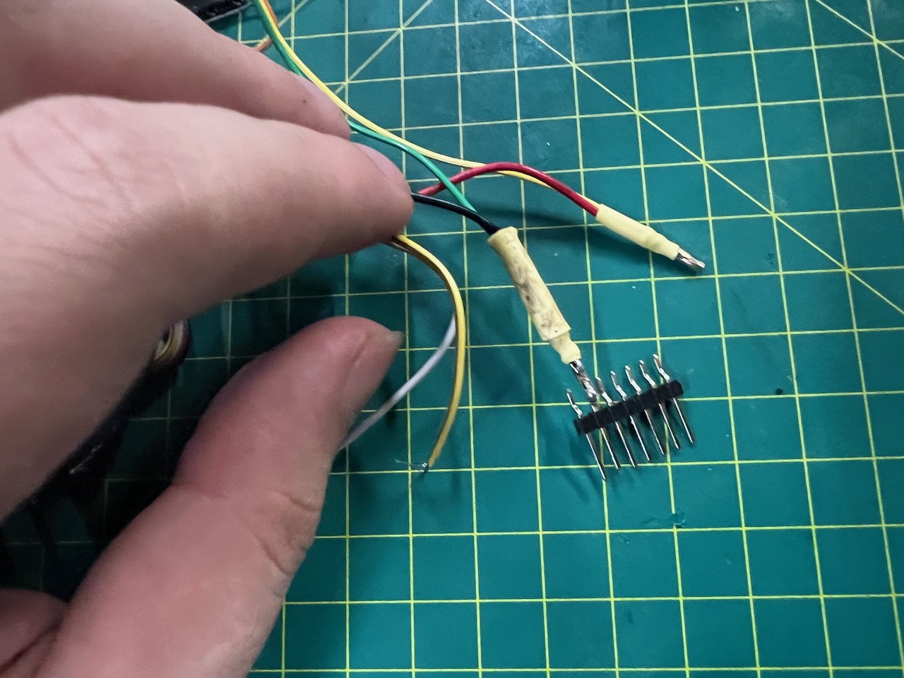
After completing this circuit board, I soldered the other components together using flying wires, including the photoresistor and the Neopixels ring.

Embedding program and Testing
Total Iterations: The project underwent a total of 20 iterations.
Input Components
- Photoresistor and DHT11: Sensors for environmental data.
- WiFi Connection: Used for time synchronization.
Output Components
NeoPixel Ring: Used for visual display of information.
Development Process
- Extensive Iterations: The project involved many lengthy iterations.
- Bug Fixes: Numerous bugs were identified and corrected throughout the development process.
#include <Adafruit_NeoPixel.h>
#include <DHT.h>
#include <WiFi.h>
#include <time.h>
#define PIN_NEOPIXEL D9 // NeoPixel连接的GPIO引脚D9
#define NUMPIXELS 12
#define DELAYVAL 150
#define LIGHT_SENSOR_PIN A8 // 光线传感器连接的模拟输入引脚A8
#define DHTPIN D6 // DHT11传感器连接的GPIO引脚D6
#define DHTTYPE DHT11 // DHT11传感器类型
#define WIFI_SSID "4536251" // Wi-Fi网络名
#define WIFI_PASSWORD "EACTJB159357" // Wi-Fi密码
Adafruit_NeoPixel pixels(NUMPIXELS, PIN_NEOPIXEL, NEO_GRB + NEO_KHZ800);
DHT dht(DHTPIN, DHTTYPE);
void setup() {
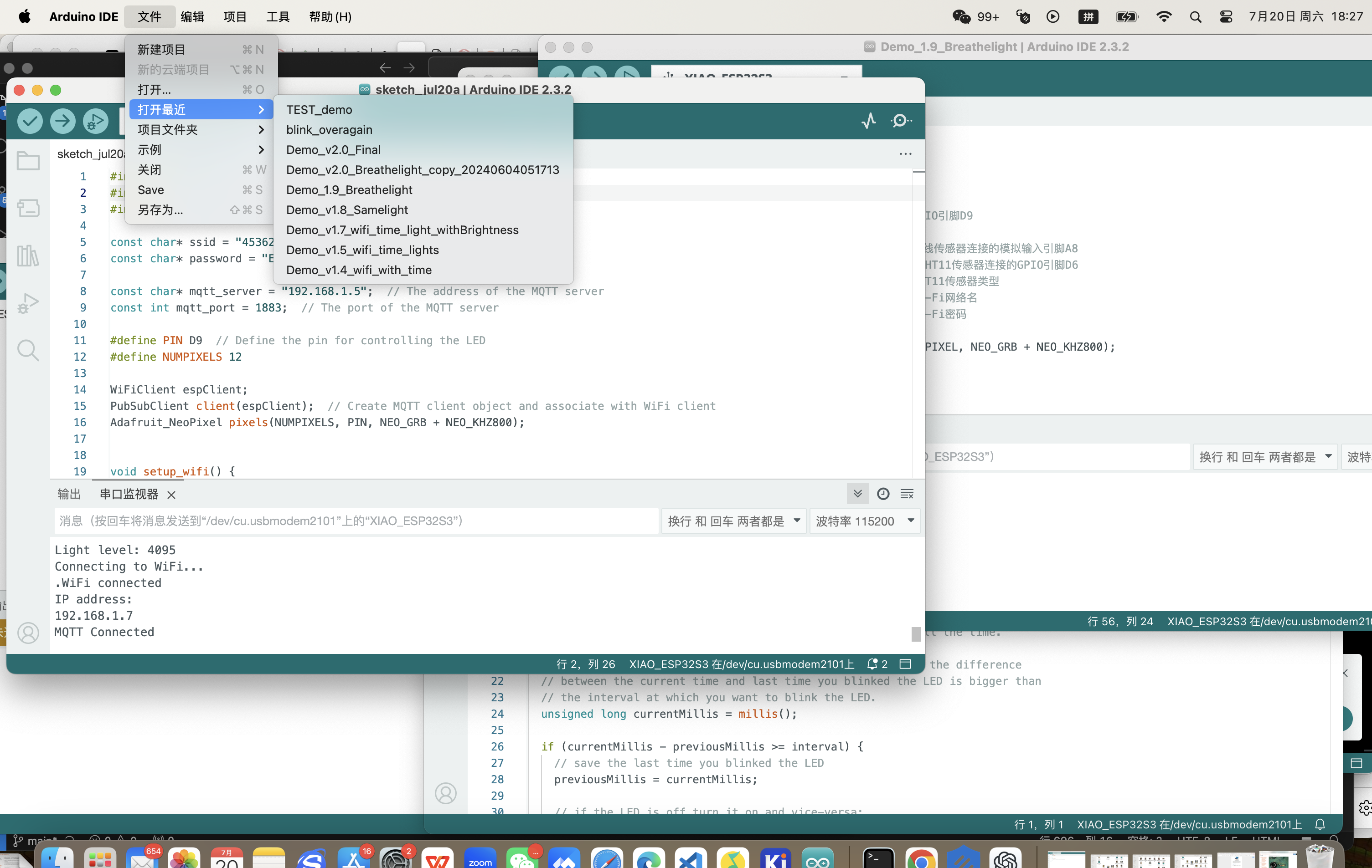
Serial.begin(115200);
pixels.begin(); // 初始化NeoPixel条
pinMode(LIGHT_SENSOR_PIN, INPUT); // 设置光线传感器引脚为输入
dht.begin(); // 初始化DHT11传感器
connectToWiFi(); // 连接到Wi-Fi网络
configTime(8 * 3600, 0, "pool.ntp.org", "time.nist.gov"); // 配置时区为北京时间UTC+8
}
void loop() {
int lightLevel = analogRead(LIGHT_SENSOR_PIN); // 读取光线强度
int brightness = map(lightLevel, 800, 4095, 0, 255); // 映射光线强度到亮度值
pixels.setBrightness(brightness); // 设置LED亮度
showHourlyLED(); // 显示常规时辰LED
printSensorData(); // 打印传感器数据
delay(5000); // 每10s更新一次
}
void connectToWiFi() {
Serial.println("Attempting to connect to WiFi network...");
Serial.print("Connecting to ");
Serial.println(WIFI_SSID);
WiFi.begin(WIFI_SSID, WIFI_PASSWORD);
int ledIndex = 0; // 初始LED索引
while (WiFi.status() != WL_CONNECTED) {
delay(150);
Serial.print(".");
lightLEDInSequence(ledIndex); // 点亮LED形成转圈效果
ledIndex = (ledIndex + 1) % NUMPIXELS; // 更新LED索引
}
// WiFi连接成功后,所有LED长亮5秒
pixels.fill(pixels.Color(0, 255, 0)); // 设置所有LED为绿色
pixels.show();
delay(5000); // 长亮5秒
Serial.println("");
Serial.println("WiFi connected.");
Serial.println("IP address: ");
Serial.println(WiFi.localIP());
}
void lightLEDInSequence(int ledIndex) {
pixels.clear();
pixels.setPixelColor(ledIndex, pixels.Color(50, 50, 50)); // 设置为柔弱的白光
pixels.show();
}
void showHourlyLED() {
float temp = dht.readTemperature(); // 读取温度值(摄氏度)
float humidity = dht.readHumidity(); // 读取湿度百分比
if (temp > 18 && temp < 37 && humidity > 30 && humidity < 60) {
breatheLights(); // 在舒适条件下展示呼吸灯效果
} else {
time_t now = time(nullptr);
struct tm timeinfo;
if (!getLocalTime(&timeinfo)) {
Serial.println("Failed to obtain time");
return;
}
// 打印当前时间
char buffer[20];
strftime(buffer, sizeof(buffer), "%Y-%m-%d %H:%M:%S", &timeinfo);
Serial.print("Synced time: ");
Serial.println(buffer);
int hour = timeinfo.tm_hour;
int shichenIndex = (hour + 1) / 2 % 12; // 计算当前时辰
uint32_t color = getColorForShichen(shichenIndex); // 获取当前时辰的颜色
pixels.clear();
for (int i = 0; i <= shichenIndex; i++) {
pixels.setPixelColor(i, color); // 使用统一颜色设置点亮的LED
}
pixels.show();
}
}
void breatheLights() {
time_t now = time(nullptr);
struct tm timeinfo;
if (!getLocalTime(&timeinfo)) {
Serial.println("Failed to obtain time");
return;
}
int hour = timeinfo.tm_hour % 12; // 获取12小时制的小时数
uint32_t color = getColorForShichen((hour == 0 ? 12 : hour) - 1); // 获取当前时辰的颜色
int maxBrightness = 255; // 最大亮度值
int minBrightness = 30; // 最小亮度值
int steps = 30; // 控制波浪流动的步长
// 提取颜色的红、绿、蓝组成部分
uint8_t r = (uint8_t)((color >> 16) & 0xFF);
uint8_t g = (uint8_t)((color >> 8) & 0xFF);
uint8_t b = (uint8_t)(color & 0xFF);
// 增加亮度的循环
for (int brightness = minBrightness; brightness <= maxBrightness; brightness += 5) {
for (int i = 0; i <= hour; i++) {
pixels.setPixelColor(i, pixels.Color(r * brightness / maxBrightness, g * brightness / maxBrightness, b * brightness / maxBrightness));
}
pixels.show();
delay(30); // 控制波浪速度
}
// 减少亮度的循环
for (int brightness = maxBrightness; brightness >= minBrightness; brightness -= 5) {
for (int i = 0; i <= hour; i++) {
pixels.setPixelColor(i, pixels.Color(r * brightness / maxBrightness, g * brightness / maxBrightness, b * brightness / maxBrightness));
}
pixels.show();
delay(30); // 控制波浪速度
}
}
uint32_t getCurrentHourColor() {
time_t now = time(nullptr);
struct tm timeinfo;
if (!getLocalTime(&timeinfo)) {
Serial.println("Failed to obtain time");
return pixels.Color(255, 255, 255); // 默认白色
}
int hour = timeinfo.tm_hour % 12; // 获取12小时制的小时数
return getColorForShichen((hour == 0 ? 12 : hour) - 1); // 获取当前时辰的颜色
}
void printSensorData() {
float temp = dht.readTemperature(); // 读取温度值(摄氏度)
float humidity = dht.readHumidity(); // 读取湿度百分比
int lightLevel = analogRead(LIGHT_SENSOR_PIN); // 读取光线强度
Serial.println("Current sensor readings:");
Serial.printf("Temperature: %.2f C\n", temp);
Serial.printf("Humidity: %.2f %%\n", humidity);
Serial.printf("Light level: %d\n", lightLevel);
}
uint32_t getColorForShichen(int index) {
switch (index) {
case 0: return pixels.Color(0, 0, 0); // 子时 - 玄黑
case 1: return pixels.Color(74, 66, 102); // 丑时 - 黛色
case 2: return pixels.Color(61, 59, 79); // 寅时 - 鸦青
case 3: return pixels.Color(237, 87, 54); // 卯时 - 妃色
case 4: return pixels.Color(255, 241, 67); // 辰时 - 藤黄
case 5: return pixels.Color(249, 144, 111); // 巳时 - 酡颜
case 6: return pixels.Color(157, 41, 51); // 午时 - 胭脂
case 7: return pixels.Color(72, 192, 163); // 未时 - 天水碧
case 8: return pixels.Color(217, 182, 17); // 申时 - 秋香
case 9: return pixels.Color(115, 151, 171); // 酉时 - 花青
case 10: return pixels.Color(93, 81, 60); // 戌时 - 相思灰
case 11: return pixels.Color(214, 236, 240); // 亥时 - 月白
default: return pixels.Color(255, 255, 255); // 默认 - 白色
}
}
Current Status of the Project
This program is still some distance from achieving my final goals. I will continue to enhance and develop additional functionalities on my development board, Final Project Darklock.
Planned Enhancements
- Continued Development: I plan to continue working on the features that are not yet completed.
- Camera Functionality: I have retained the camera functionality in the development process, which might likely incorporate AI vision recognition technologies in the future to enhance performance.
Future Directions
Here are the activities I plan to undertake to advance the project:
- Implementing and testing the unfinished features of the project.
- Exploring and potentially integrating AI vision recognition to elevate the project's capabilities.
- ID&MD Design: The_DAO_Clock.stl
- Dao Clock PCB Files:DownloadThe Dao Clock PCB Files.zip
- coding files: Final Code
I will continue to research for suitable TinyML models and will update this section as soon as I have a suitable model.
I will also continue to work on the documentation and presentation of the final project.
Original design files of my final project
Final project presentation
Epilogue
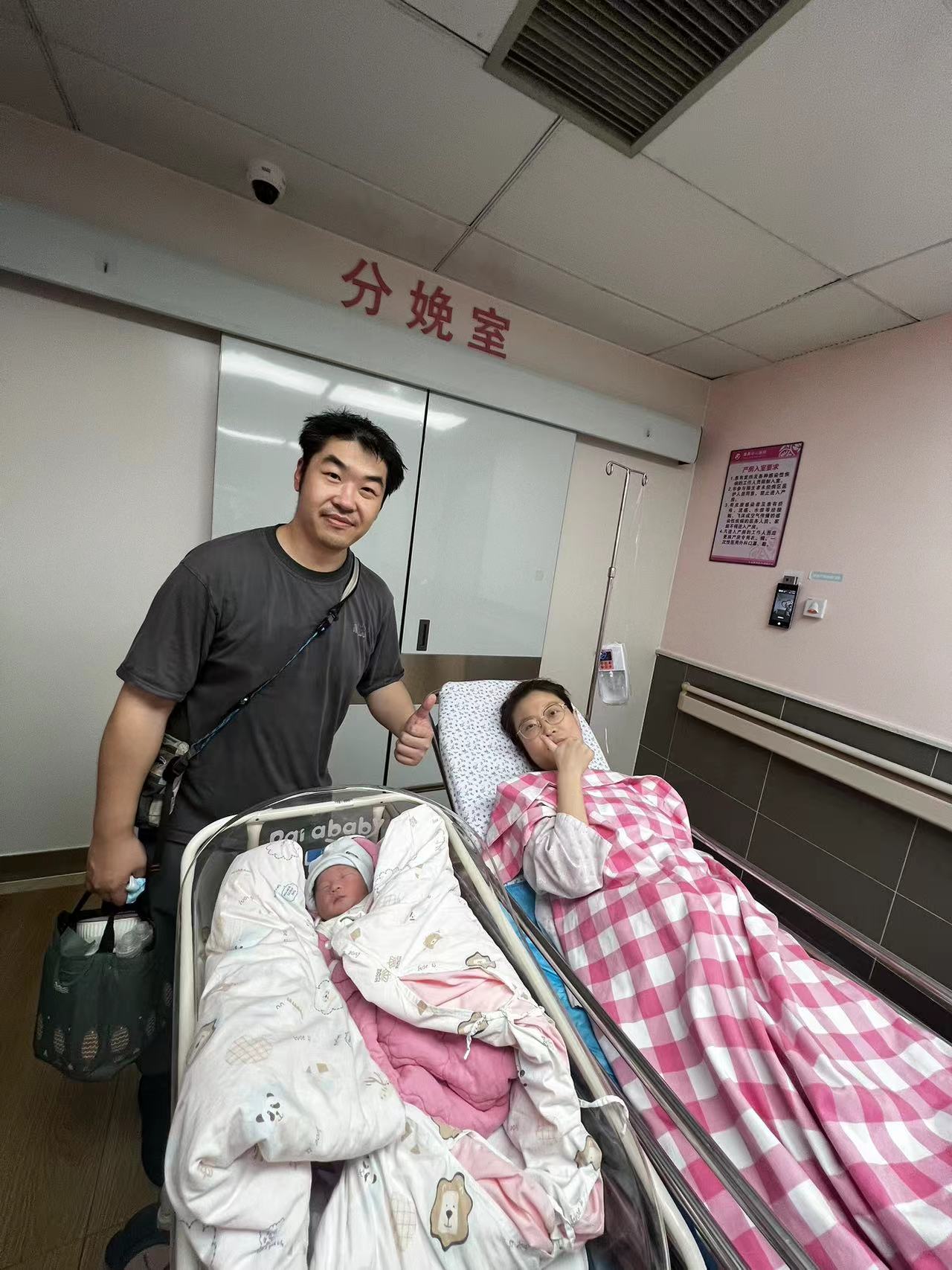
The journey of Fab has been a deeply memorable phase of my life. While I was engaged in the Final Project, a significant event occurred— the birth of my beautiful daughter. During this period, I was at the hospital, taking care of my wife and baby.
Her arrival slightly delayed my progress on the Final Project, but it brought me immense joy. Perhaps, the real Final Project was the wonderful little angel bestowed upon me by God, which will remain the grandest project of my life.
In the journey of Fab, this will stand out as the most cherished memory of my life.